Section IV
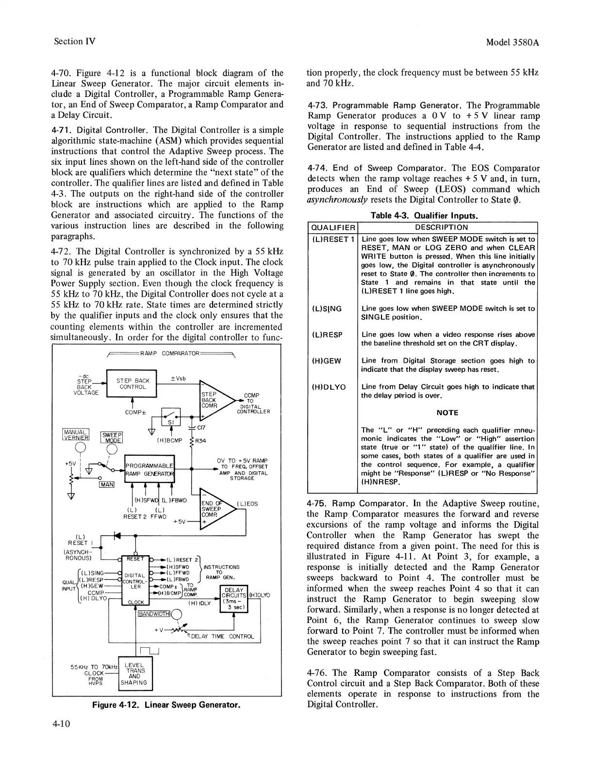
4-70. Figure 4-12 is a functional block diagram
of
the
Linear Sweep Generator. The major circuit elements in-
clude a Digital Controller, a Programmable Ramp Genera-
tor, an End
of
Sweep Comparator, a Ramp Comparator and
a Delay Circuit.
4-71. Digital Controller. The Digital Controller
is
a simple
algorithmic state-machine (ASM) which provides sequential
instructions that control the Adaptjve Sweep process. The
six input lines shown on the left-hand side
of
the controller
block are qualifiers which determine the
"next
state"
of
the
controller. The qualifier lines are listed and defined in Table
4-3. The outputs on the right-hand side
of
the controller
block are instructions which are applied to the Ramp
Generator and associated circuitry. The functions
of
the
various instruction lines are described in the following
paragraphs.
4-72. The Digital Controller is synchronized by a
55
kHz
to 70 kHz pulse train applied to the Clock input. The clock
signal
is
generated by an oscillator in the High Voltage
Power Supply section. Even though the clock frequency
is
55
kHz to 70 kHz, the Digital Controller does
not
cycle at a
55
kHz to 70 kHz rate. State times are determined strictly
by the qualifier inputs and the clock only ensures that the
counting elements within the controller are incremented
simultaneously. In order for the digital controller to func-
F===RAMP
COMPARATOR====-.
STEP
BACK
CONTROL
(L)
RESET I
(ASYNCH-
RONOUS)
ISWITP1
LMooEJ
0
I
I
COMP±
LEVEL
TRANS
AND
55KHz
TO
70kHz
CLOCK
FROM
HVPS
SHAPING
±Vsb
+5V
(L
)RESET
2}
( H
)SFWD
INSTRUCTIONS
(L)FFWD
TC
( L
)"FBWD
RAMP
GEN.
COMP±
lR1~P
DELAY
H)BCMPJcoMP.
CIRCUITS
(H)DLYO
(H)
IDLY
(3ms-
3 sec)
+v~.,,.,.,,~~~~~
DELAY
TIME
CONTROL
Figure 4-12. Linear Sweep Generator.
4-10
Model 3580A
tion properly, the clock frequency must be between
55
kHz
and 70 kHz.
4-73. Programmable Ramp Generator. The Programmable
Ramp Generator produces a 0 V to + 5 V linear ramp
voltage in response to sequential instructions from the
Digital Controller. The instructions applied to the Ramp
Generator are listed and defined in Table 4-4.
4-74. End of Sweep Comparator. The
BOS
Comparator
detects when the ramp voltage reaches + 5 V and, in turn,
produces
an
End
of
Sweep (LEOS) command which
asynchronously resets the Digital Controller
to
State
r/J.
Table 4-3. Qualifier Inputs.
QUALIFIER DESCRIPTION
(L)RESET 1 Line goes low when SWEEP MODE switch
is
set
to
RESET,
MAN
or
LOG
ZERO
and
when CLEAR
WRITE
button
is
pressed. When
this
line initially
goes low,
the
Digital
controller
is
asynchronously
reset
to
State(}).
The
controller
then
increments
to
State
1
and
remains in
that
state
until
the
(L)RESET 1 line goes high.
IUS!NG
Line goes low when SWEEP MODE switch
is
set
to
SINGLE position.
(L)RESP Line goes low when a video response rises above
the
baseline threshold
set
on
the
CRT
display.
(H)GEW
(H)DLYO
Line from Digital Storage section goes high
to
indicate
that
the
display sweep has reset.
Line
from
Delay Circuit goes high
to
indicate
that
the
delay period
is
over.
NOTE
The
"L"
or
"H"
preceding each qualifier mneu-
monic indicates
the
"Low"
or
"High"
assertion
state
(true
or
"1"
state)
of
the
qualifier line. In
some cases,
both
states
of
a qualifier are used in
the
control
sequence.
For
example,
a qualifier
might
be
"Response"
(L)RESP
or
"No
Response"
(H)NRESP.
4-75. Ramp Comparator. In the Adaptive Sweep routine,
the Ramp Comparator measures the forward and reverse
excursions
of
the ramp voltage and informs the Digital
Controller when the Ramp Generator has swept the
required distance from a
given
point. The need for this
is
illustrated in Figure 4-11. At Point 3, for example, a
response
is
initially detected and the Ramp Generator
sweeps backward to Point 4. The controller must
be
informed when the sweep reaches Point 4
so
that it can
instruct the Ramp Generator to begin sweeping slow
forward. Similarly, when a response is no longer detected at
Point 6, the Ramp Generator continues
to
sweep slow
forward
to
Point 7. The controller must be informed when
the sweep reaches point 7
so
that
it can instruct the Ramp
Generator
to
begin sweeping fast.
4-76. The Ramp Comparator consists
of
a Step Back
Control circuit and a Step Back Comparator. Both
of
these
elements operate in response to instructions from the
Digital Controller.