Model 3580A
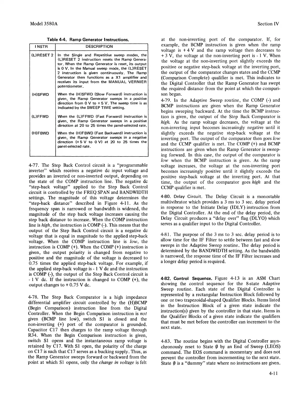
Table 4-4. Ramp Generator Instructions.
INSTR
DESCRIPTION
(L)RESET 2
In
the
Single and Repetitive sweep modes,
the
(L)RESET
2 .instruction resets
the
Ramp Genera-
tor.
When the Ramp Generator
is
reset, its
output
is
0 V.
In
the
Manual sweep mode,
the
(L)RESET
2 instruction
is
given continuously. The Ramp
Generator
then
functions as a
X1
amplifier and
receives its input from
the
MANUAL VERNIER
potentiometer.
(H)SFWD When
the
(H)SFWD (Slow Forward) instruction
is
given,
the
Ramp Generator sweeps
in
a positive
direction from 0 V
to
+ 5 V. The sweep time
is
as
indicated
by
the
SWEEP TIME setting.
(L)FFWD When
the
(L)FFWD (Fast Forward) instruction
is
given,
the
Ramp Generator sweeps
in
a positive
direction
at
20
to
25
times
the
panel-selected rate.
(H)FBWD When
the
(H)FBWD (Fast Backward) instruction is
given,
the
Ramp
Generator sweeps in a negative
direction
(+
5 V
to
0
V)
at
20
to
25
times
the
panel-selected rate.
4-77. The Step Back Control circuit
is
a "programmable
inverter" which receives a negative de input voltage and
provides an inverted or non-inverted output, depending on
the state
of
the
COMP
instruction line. The negative
de
"step-back voltage" applied
to
the Step Back Control
circuit
is
controlled by the FREQ
SP
AN
and BANDWIDTH
settings. The magnitude
of
this voltage determines the
"step-back distance" described in Figure 4-11.
As
the
frequency span
is
narrowed or bandwidth is widened, the
magnitude
of
the step back voltage increases causing the
step back distance
to
increase. When the
COMP
instruction
line is high, the instruction is COMP(-). This means
that
the
output
of
the Step Back Control circuit
is
a negative
de
voltage
that
is
equal in magnitude
to
the applied step-back
voltage. When the
COMP
instruction line
is
low, the
instruction is COMP(+).
When
the COMP(+) instruction
is
given, the outpu.t polarity
is
changed from negative to
positive and the magnitude
of
the voltage is decreased
to
0.75 times the applied step-back voltage. For example,
if
the applied step-back voltage is - 1 V de and the instruction
is COMP(-), the output
of
the Step Back Control circuit is
- 1 V de.
If
the instruction is changed to
COMP
(+), the
output changes
to+
0.75 V de.
4-78. The Step Back Comparator is a high impedance
differential amplifier circuit controlled by the
(H)BCMP
(Begin Comparison) illstruction line from the Digital
Controller.
When
the Begin Comparison instruction is
not
given
(BCMP
line low), switch
Sl
is
closed and the
non-inverting (
+)
port
of
the comparator
is
grounded.
Capacitor
Cl
7 then charges to the ramp voltage through
R34. When the
Begin
Comparison instruction is given,
switch
Sl
opens and the instantaneous ramp voltage
is
retained by
Cl
7. With
Sl
open, the polarity
of
the charge
on
Cl
7
is
such that
Cl
7 serves
as
a bucking supply. Thus,
as
the Ramp Generator sweeps forward
or
backward from the
point at which
Sl
opens, only the change in voltage
il'
felt
Section IV
at the non-inverting port
of
the comparator.
If,
for
example, the
BCMP
instruction
is
given
when the ramp
voltage
is
+ 4 V and the ramp voltage then decreases to
+ 3
V,
the voltage at the non-inverting port
is
- 1 V. When
the voltage at the non-inverting port slightly exceeds the
positive or negative step-back voltage
at
the inverting port,
the output
of
the comparator changes states and the
CCMP
(Comparison Complete) qualifier
is
met. This indicates to
the Digital Controller
that
the Ramp Generator has swept
the required distance from the point
at
which the compari-
son began.
4-79. In the Adaptive Sweep routine, the
COMP
(-)and
BCMP
instructions are
given
when the Ramp Generator
begins sweeping backward. At the time the
BCMP
instruc-
tion
is
given, the output
of
the Step Back Comparator
is
high.
As
the ramp voltage decreases, the voltage at the
non-inverting input becomes increasingly negative until it
slightly exceeds the negative step-back voltage at the
inverting port. The output
of
the comparator then
goes
low
and the
CCMP
qualifier
is
met. The COMP(+) and
BCMP
instructions are given when the Ramp Generator is sweep-
ing
forward. In this case, the output
of
the comparator
is
low when the
BCMP
instruction
is
given.
As
the ramp
voltage increases, the voltage at the non-inverting port
becomes increasingly positive until
it
slightly exceeds the
positive step-back voltage at the inverting port. At that
time, the output
of
the comparator goes high and the
CCMP
qualifier
is
met.
4-80.
Delay
Circuit. The Delay Circuit
is
a monostable
multivibrator which provides a 3 ms
to
3 sec. delay period
in response to the Initiate Delay (IDLY) instruction from
the Digital Controller. At the end
of
the delay period, the
Delay Circuit produces a "delay over" flag (DLYO) which
serves
as
a qualifier input to the Digital Controller.
4-81. The
purpo~e
of
the 3 ms
to
3 sec. delay period is
to
allow time for the IF Filter to settle between fast and slow
sweeps in the Adaptive Sweep routine. The delay period
is
determined by the BANDWIDTH setting.
As
the bandwidth
is
narrowed, the response time
of
the
IF
Filter increases and
a longer delay period
is
required.
4-82. Control
Sequence.
Figure 4-13
is
an
ASM
Chart
showing the control sequence for the 8-state Adaptive
Sweep routine. Each state
of
the Digital Controller
is
represented by a rectangular Instruction Block followed by
one or two trapezoidal-shaped Qualifier Blocks. Items listed
in the Instruction Block
of
a given state indicate the
instruction(s) given by the controller
in
that state. Items in
the Qualifier Blocks
of
a given state indicate the qualifiers
that must be met before the controller can increment to the
next state.
4-83.
The
routine begins with the Digital Controller asyn-
chronously reset to State
'/J
by an End
of
Sweep (LEOS)
command. The EOS command
is
momentary and does
not
prevent the controller from incrementing
to
the next state.
State
'/J
is
a
"dummy"
state where no instructions are given.
4-11