Model
3580A
BASIC
OPERATING
PROCEDURES
Section III
e.
Connect the probe tip to the rear panel TRACKING
OSC
OUT
connector. Connect the ground lead
of
the probe
to
case
ground.
f.
Adjust the front panel amplitude VERNIER
so
that
the horizontal trace
is
between 0
dB
and - 10
dB
on the
display.
g.
Set the AMPLITUDE
MODE
to
LOG
I dB/DIV.
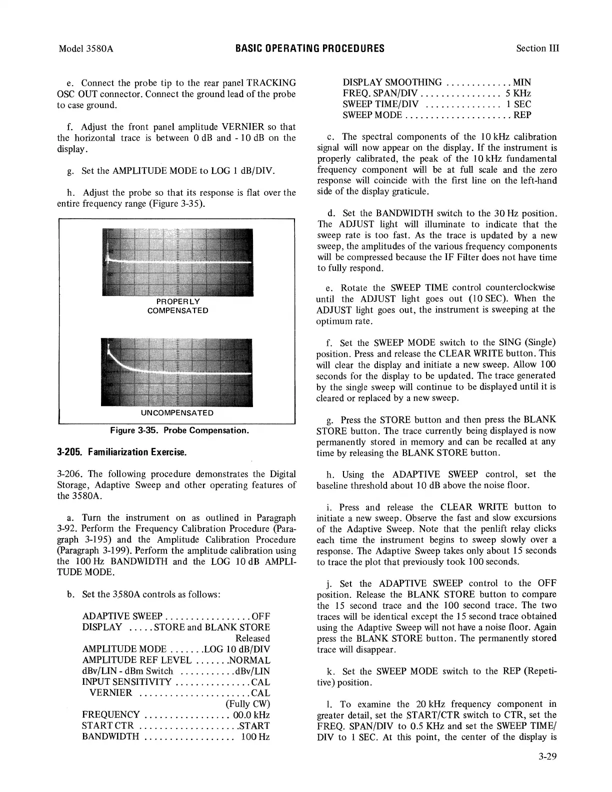
h. Adjust the probe
so
that its response
is
flat over the
entire frequency range (Figure 3-35).
PROPERLY
COMPENSATED
UNCOMPENSATED
Figure 3-35. Probe Compensation.
3-205.
Familiarization
Exercise.
3-206. The following procedure demonstrates the Digital
Storage, Adaptive Sweep and other operating features
of
the 3580A.
a. Turn the instrument on
as
outlined in Paragraph
3-92. Perform the Frequency Calibration Procedure (Para-
graph 3-195) and the Amplitude Calibration Procedure
(Paragraph 3-199). Perform the amplitude calibration using
the 100
Hz
BANDWIDTH
and the
LOG
10
dB
AMPLI-
TUDE
MODE.
b. Set the 3.580A controls
as
follows:
ADAPTIVE
SWEEP
.................
OFF
DISPLAY
.....
STORE and BLANK STORE
Released
AMPLITUDE
MODE
.......
LOG
10 dB/DIV
AMPLITUDE REF LEVEL
.......
NORMAL
dBv/LIN -
dBm
Switch
...........
dBv/LIN
INPUT SENSITIVITY
...............
CAL
VERNIER
......................
CAL
(Fully
CW)
FREQUENCY
................•
00.0 kHz
START CTR
....................
START
BANDWIDTH
. . . . . . . . . . . . . . . . . . 100
Hz
DISPLAY SMOOTHING
.............
MIN
FREQ. SPAN/DIV
................
5
KHz
SWEEP
TIME/DIV . . . . . . . . . . . . . . . 1
SEC
SWEEP
MODE
....................•
REP
c. The spectral components
of
the 10 kHz calibration
signal
will
now appear on the display.
If
the instrument
is
properly calibrated, the peak of the 10 kHz fundamental
frequency component
will
be at full scale and the zero
response
will
coincide with the first line on the left-hand
side
of
the display graticule.
d. Set the
BANDWIDTH
switch
to
the
30
Hz
position.
The
ADJUST light will illuminate
to
indicate
that
the
sweep rate
is
too fast.
As
the trace
is
updated by a new
sweep, the amplitudes
of
the various frequency components
will
be
compressed because the IF Filter does not have time
to
fully respond.
e. Rotate the
SWEEP
TIME control counterclockwise
until the ADJUST light goes out (10 SEC).
When
the
ADJUST light
goes
out, the instrument
is
sweeping at the
optimum rate.
f. Set the
SWEEP
MODE
switch to the SING (Single)
position. Press and release the CLEAR WRITE button. This
will
clear the display and initiate a new sweep. Allow 100
seconds for the display to
be
updated. The trace generated
by the
single
sweep
will
continue to be displayed until it
is
cleared or replaced by a new sweep.
g.
Press the STORE button and then press the BLANK
STORE button. The trace currently being displayed
is
now
permanently stored in memory and can be recalled at any
time by releasing the BLANK STORE button.
h.
Using
the ADAPTIVE
SWEEP
control, set the
baseline threshold about 10
dB
above the noise floor.
i. Press and release the CLEAR
WRITE
button
to
initiate a new sweep. Observe the fast and slow excursions
of
the Adaptive Sweep. Note that the penlift relay clicks
each time the instrument begins
to
sweep slowly over a
response. The Adaptive Sweep takes only about
15
seconds
to trace the plot that previously took 100 seconds.
j. Set the ADAPTIVE
SWEEP
control
to
the OFF
position. Release the BLANK STORE button to compare
the
15
second trace and the 100 second trace. The two
traces will be identical except the
15
second trace obtained
using the Adaptive Sweep will not have a noise floor. Again
press the
BLANK
STORE button. The permanently stored
trace
will
disappear.
k. Set the
SWEEP
MODE
switch to the REP (Repeti-
tive) position.
I. To examine the 20 kHz frequency component in
greater detail, set the START/CTR switch
to
CTR, set the
FREQ. SPAN/DIV
to
0.5
KHz
and set the
SWEEP
TIME/
DIV to 1
SEC.
At
this point, the center
of
the display
is
3-29