Model
3580A
Section
IV
OV
TO
+5V
~---------------------------------~LINE~
0
RAMP
DIGITAL
STORAGE
SECTION
I
I
I
+r~
SWEEP
TIME/DIV
~
I
DV
T0+5V
\
RAMP
p==F~~~U~~~6
f
1
1:,SET===.._
L~EAR
~
IOK
SWEEP
GEN',_--~.,,,,..,--
(P/O A
3
)
ISTARTI
+!5V \ I
OV
TO
+5V
40K
FREQUENCY
~~~
g[T.1------4
(L)
T~ATA
(P/0 Al6)
~tr,'J:kE
=DIAL
MIXING=
r--
AMP.
(P/O
Al6
-
---..
IOOkHz
TO
150kHz
I
<,,
,
....
,,
R3
SWEEP
7o5K
MODE
r---'Vlllr-----,
i i
,9
I
'~~-
/
..-v""To,......,A,..N..,.D""'
C>
__
__,_.'<>--~-1
TRACK
ING
f
osc.
TO
INPUT
MIXER
PIO
SWEEP
MODE
Q
(L)
RESET 2
START
=OV
TO
-
GV
I
·CTR
=+3V
TO
-3V
6
OV
=
DIAL
FREQ.
:~
7
(PIO
A2)
OVTO
+9V
OHz
TO
50KHz
+IOV
:TRACKING]
L.
_Q.s_g,_
_J
I
I
(L)LOG
3580A-R-
3605
LOG
SWEEP
GEN
(PIO
A3)
+3o6mV
TO
+7o75V EXPONENTIAL
RAMP
FREQ
SPAN/
DIV
OV
TO
3o6V=
+ 3.SV
"2-'ottz
1D
50kHz
i c) 1
..
,,,,'"''
[bQ§J
f
I
\
I
-IOV
6
!ZERO
CALI
Figure 4-10. Frequency and Sweep Section.
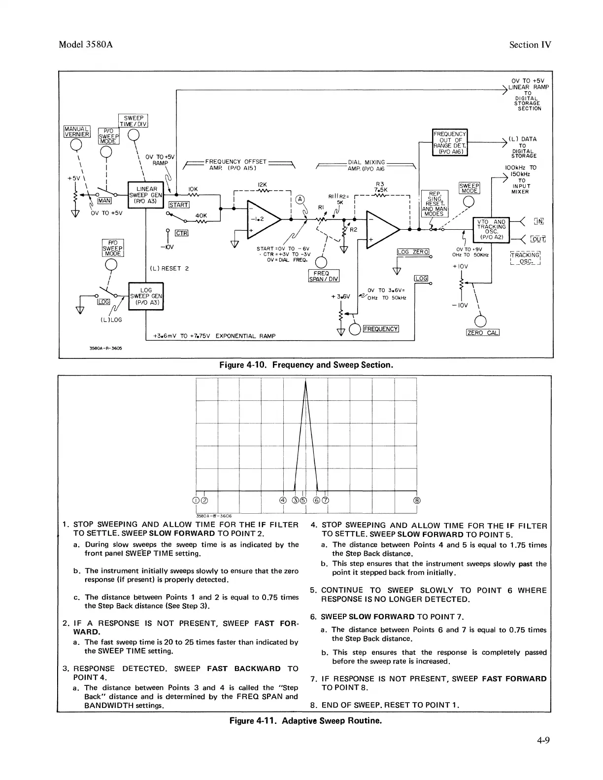
1.
STOP SWEEPING AND ALLOW TIME FOR THE IF
Fl
LTER
TO SETTLE. SWEEP SLOW FORWARD TO POINT
2.
a.
During slow sweeps the sweep
time
is
as indicated by
the
front
panel
SWE.EP
TIME setting.
b.
The instrument initially sweeps slowly
to
ensure
that
the
zero
response (if present)
is
properly
detected.
c. The distance between Points 1 and 2 is equal
to
0.75
times
the
Step
Back distance (See
Step
31.
2.
IF A RESPONSE
IS
NOT PRESENT, SWEEP FAST FOR-
WARD.
a.
The
fast sweep
time
is
20
to
25
times faster than indicated by
the
SWEEP TIME setting.
3.
RESPONSE DETECTED. SWEEP FAST BACKWARD TO
POINT4.
a.
The distance between Points 3
and
4
is
called
the
"Step
Back" distance
and
is
determined by
the
FREQ
SPAN and
BANDWIDTH settings.
®
j
4. STOP SWEEPING AND ALLOW TIME FOR THE IF FILTER
TO SETTLE. SWEEP SLOW FORWARD TO POINT
5.
a. The distance between Points 4
and
5
is
equal
to
1.75 times
the
Step
Back distance.
b.
This step ensures
that
the
instrument sweeps slowly past
the
point
it
stepped back from initially.
5.
CONTINUE TO SWEEP SLOWLY TO POINT 6 WHERE
RESPONSE IS
NO
LONGER DETECTED.
6. SWEEP SLOW FORWARD TO POINT
7.
a.
The distance between Points 6 and 7
is
equal
to
0.75
times
the
Step
Back distance.
b.
This step ensures
that
the
response
is
completely passed
before
the
sweep rate
is
increased.
7. IF RESPONSE
IS
NOT PRESENT, SWEEP FAST FORWARD
TO
POINTS.
8.
END OF SWEEP. RESET TO POINT
1.
Figure 4-11. Adaptive Sweep Routine.
4-9