Section IV
VTO frequency. The frequency range
of
the log sweep
is
from 20
Hz
to
43 kHz. During log sweeps, the
SWEEP
TIME
control
is
disabled and the Linear Sweep Generator
is
automatically set for a 5 second sweep time. The Log
Sweep Generator
is
synchronized by the (L)Reset 2
instruction from the Linear Sweep Generator.
A
(Ll
RESET 2
(FROM
LINEAR
SWEEP
GENERATOR)
B
,-----'>Nv-
- -
----,+FEEDBACK
:
~;t
v
I I
_
__,.--___,
I
I
+3.6mV
TO
+7.75V
·>----<>----EXPONENTIAL
RAMP
l[
GAINATPOINT@
.-~.-R
77
•-I
JI
R1N
R78
GAIN
AT+
PORT•
I+
~:N
•
I+~~~
•+2
-
+7.75V
(43kHz)
-
+3.6mV
I..--""'
5
SEC
(
20
Hz)
(TO
VTOl
3580A-B·
3568
Figure 4-17.
Basic
Log
Sweep
Generator.
4-109. Figure 4-l
7A
shows the basic circuit configuration
for the Log Sweep Generator. The major circuit element
is
a high input-impedance operational amplifier. The
gain
of
the amplifier with respect to Point A
is
- 1 and the
gain
at
the non-inverting port
is
+ 2. At the beginning
of
the log
sweep the following conditions exist:
a. The (L) Reset 2 line
is
low.
b. FET switch Q32
is
closed.
c.
The non-inverting port
of
the amplifier
is
grounded
through Q32.
d. Capacitor C 14
is
fully discharged.
e.
The output voltage
is
+ 3.6 mV
de
due to the
- 3.6 mV
de
reference applied to Point
A.
This sets the
analyzer frequency to 20
Hz
which
is
the starting point for
the log sweep.
When
the (L)Reset 2 instruction
is
cleared, switch Q32
opens and
Cl4
charges toward the output voltage through
feedback resistor R66.
As
C14 charges, the output voltage
becomes increasingly positive.
Due
to the bootstrapping
effect
of
the positive feedback through R66, the charge rate
of
C14 increases exponentially. The exponential ramp at
the output
is
as
shown in Figure 4-17B.
4-110. Auto Zero Circuit.
An
Auto Zero Circuit
is
in-
cluded in the
Log
Sweep Generator to null out any
de
offset introduced by the operational amplifier. The overall
circuit configuration
is
shown in Figure 4-18.
4-16
(L)RESET
2
(FROM
LINEAR
SWEEP
GENERATOR)
-
3.6mV
Reference
R66
I.BM
r------...vv------
-,
Model 3580A
I I
1 : +FEEDBACK
:
:/
' I
R78
93.1 k
I
I
I
·>---.-+3.6mV
TO
+7.75V
036
I
I
EXPONENTIAL
RAMP
(TO
VTO)
I -FEEDBACK
-
--WV--
- - - -
_J____..,-
Q35
~--~
3580A-B-3566
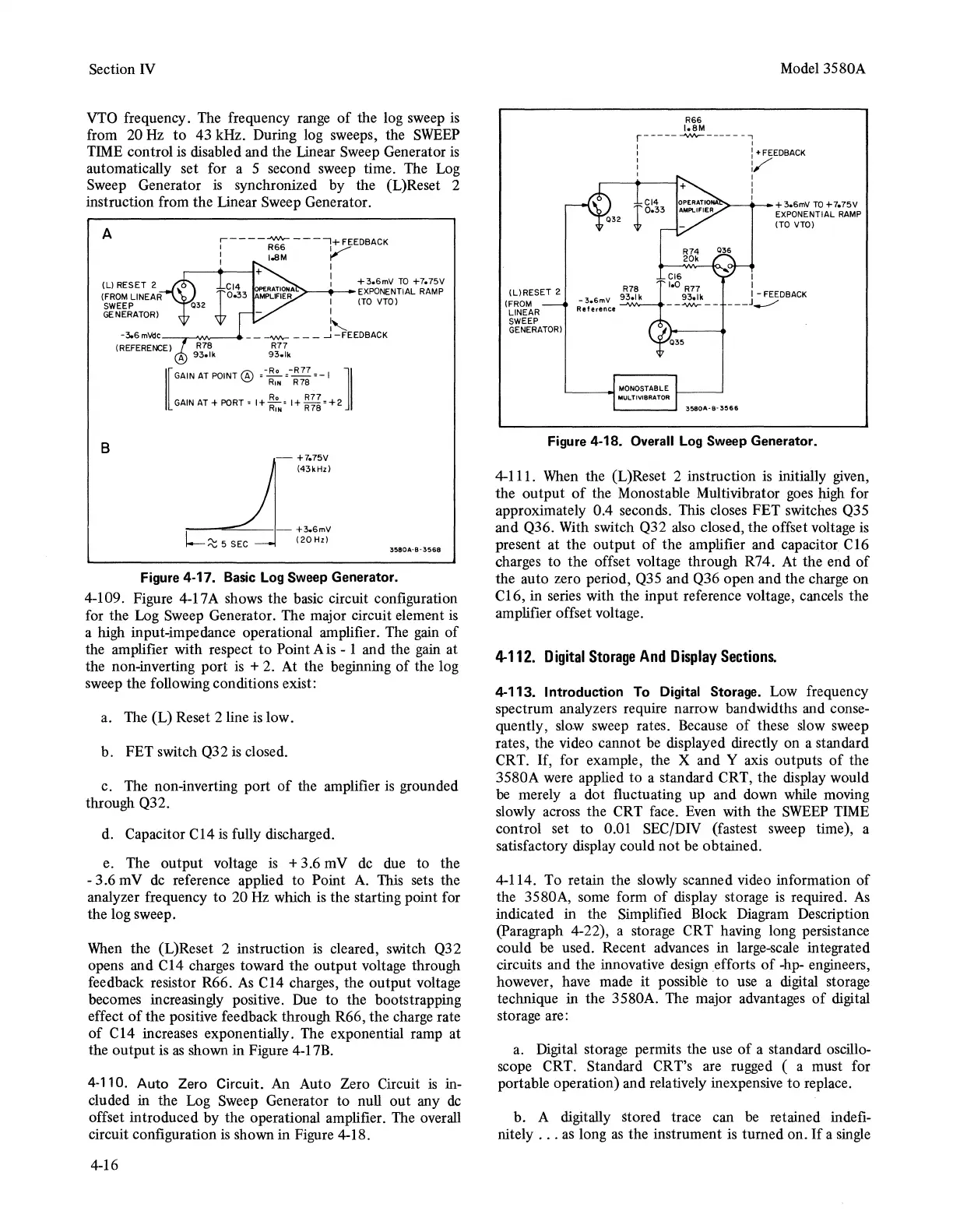
Figure 4-18. Overall
Log
Sweep
Generator.
4-111.
When
the (L)Reset 2 instruction
is
initially
given,
the output
of
the Monostable Multivibrator
goes
high for
approximately 0.4 seconds. This closes FET switches Q35
and Q36. With switch Q32
also
closed, the offset voltage
is
present at the output
of
the amplifier and capacitor C16
charges to the offset voltage through R74.
At
the end of
the auto zero period,
Q35
and Q36 open and the charge on
Cl
6, in series with the input reference voltage, cancels the
amplifier offset voltage.
4-112.
Digital
Storage
And
Display
Sections.
4-113. Introduction To Digital Storage. Low frequency
spectrum analyzers require narrow bandwidths and conse-
quently, slow sweep rates. Because
of
these slow sweep
rates, the video cannot
be
displayed directly on a standard
CRT.
If,
for example, the X and Y axis outputs
of
the
3580A were applied to a standard CRT, the display would
be
merely a dot fluctuating up and down while moving
slowly across the CRT face. Even with the
SWEEP
TIME
control set to 0.01 SEC/DIV (fastest sweep time), a
satisfactory display could not
be
obtained.
4-114. To retain the slowly scanned video information
of
the 3580A, some form
of
display storage
is
required.
As
indicated in the Simplified Block Diagram Description
(Paragraph 4-22), a storage CRT having long persistance
could
be
used. Recent advances in large-scale integrated
circuits and the innovative
design
efforts
of
-hp- engineers,
however, have made it possible to use a digital storage
technique in the 3580A. The major advantages
of
digital
storage are:
a.
Digital storage permits the use
of
a standard oscillo-
scope CRT. Standard CRT's are rugged ( a must for
portable operation) and relatively inexpensive
to
replace.
b. A digitally stored trace can
be
retained indefi-
nitely
...
as
long
as
the instrument
is
turned on.
If
a
single