Model 3580A
Section VIII
CHANGE
NO.
Ll
2
: Applies
to
instruments with the
following serial numbers:
1312A-00399 and lower
l 3 l 2A-00402
13
l 2A-00403
1312A-00405
13
l 2A-00408
l 3 l 2A-004
IO
1312A-00413
1312A-00416 thru 1409A-00515
Table 6-1: Change the High Voltage Power Supply
(A
11)
parts list
as
follows:
All
All
Al
AllHCI
A11A1C2,
C3
A11A1C4
A11A1C5
A11A1CR1,
CR2
AllAlRI
A11AIP2
*
AllA7
AllA2Cl
Al
IA2C2
AllA2C3
All
A2C4
A11A7C5
A
11
A2Ct
AllA2CRl
AllA7CR2
Al
IA2CR3
AllA2Rl
AllA2f<2
A11A?P3
Al
1A2R4
AllA2R
5
A11A2Rt
AllA7TI
03580-64201
1251-3069
1251.-3201
03580-66511
0160-~007
0160-3008
0160-3007
0160-3008
1901-0341
7100-H5q
0687-1041
035R0-66517
016<1-;007
Olo0-3008
016ll-3007
0160-3007
0160-;001
0160-2544
1902-3428
1902-H28
1902-3737
0836-0001
0687-1051
0687-lHl
0687-7271
0687-7751
0698-8427
9100-3l63
5
4
I
l
POWFR
SUPPLY-HIGH
VOLTAGE
CONNECTOR:PC 8
HALF
CONTACT
CONNECTOR: POST TYPE
3-CONTACT
POSITION
PC
ASSY:POWEA SUPPLY 1, HIGH
VOLTAGE
C:FXD
CFR
4700
PF 20%
4K
VIJCW
C:FXD
CER
4700
PF
20%
4K
VDCW
C:FXO
CER
4700
PF
20%
4K
VOCW
C:FXO
CER
4700
PF
20%
4K
VOCW
OIOOE:SI
7000
PIV
50MA
R
:VAR
CFl!MET 2
MEGOHM
70%
TYPE
Vt
l/2W
R:FXO
COMP
lOIJK
OHM
1011:
l/2W
FACTORY SELECTED PART
BOARD
ASSY:
POWER
SUPPLY
2 -
DOESN"T
INCLUDE
A11A2T1
C:FXIJ
CFR
4700
PF 20%
4K
vncw
C:Fxu
r.ER
4700
PF
202:
4K
vocw
C:FXO
CFR
470~
PF
20i
4K
VOCW
C:FXO
CER
4700
PF
20~
4K
VOCW
C:FXO
C:ER
4700
PF
20%
4K
VIJCW
C:FXD
CER
270
PF
101
lJOOVOCW
DIODE
BR
FAKOOWN:S
IL
If.ON
lOOV
5*
DIODE
8RfAKDOWN:S
IL
ICllN
lOOV
51
DIODE
81! fAKIJOWN•S
IL
ICON
20.ov
5*
R:FXO
CARl\DN
50
MEGOHM
10%
2W
R:FXD
C.OMP
1
MFGOHM
10%
l/2W
R:FXD
COMP
15K
OHM
IJI
l/2W
R:FXIJ
CCIMP
2200
OHM
101
l/2W
R:FXIJ
COMP
2.7
MfGOHM 10%
l/lW
R:FXO
MFT
HM
29
MFGOHM
10%
1.ow
TRANSFORMER:
H.V-
(INCLUDES
03580-66517)
78480
78480
27264
28480
72982
72982
72982
72982
28480
78480
01121
28480
72982
72982
72982
72982
72982
5628q
28480
284110
28480
784110
01121
01121
01121
01121
28480
28480
03580-64201
1251-3069
09-50-7031
03580-66511
3888-024-Y5S0-472M
3888-024-Y5S0-472M
3888-024-Y5S0-472M
3888-024-Y5S0-472M
1901-0341
2100-3359
EB
1041
03580-66512
3888-024-Y5S0-472M
3888-024-Y5S0-472M
3888-024-Y5SD-472M
3888-024-V5SD-472M
3888-024-Y5SD-472M
C0168102E271KS27-CDH
1902-3428
1902-3428
1902-3237
0836-0001
Ell
I
051
EB
1531
fA
2721
~fl
2751
0698-8427
9100-3263
Schematic
No.
8:
Use
the High Voltage Power Supply
schematic (Figure 8-6) in place
of
the existing schematic.
CHANGE
NO.
Ll
4
: Applies
to
instruments with serial
numbers 1415AA00740 and below.
CHANGE
NO.
A
3
: Applies to instruments with serial
numbers 1415A00935 and below.
Table 6-1,
Page
6-22. Delete A8R95 and A8R96 from the
A8
assembly parts list.
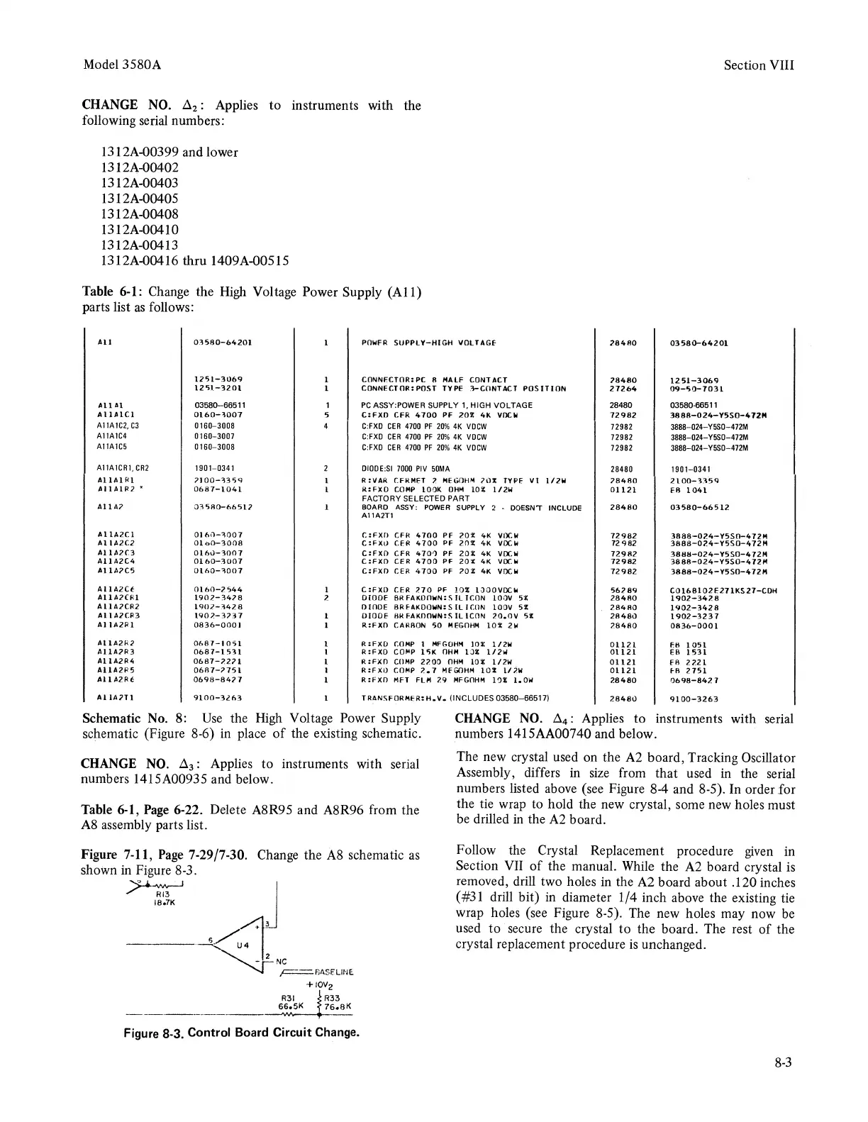
Figure 7-11,
Page
7-29/7-30.
Change the
A8
schematic
as
shown
in
Figure 8-3.
~
J
18o7K
------<(!:_,~
'~'""
+IOV2
R31
R33
66o5K
76.aK
Figure 8-3. Control Board Circuit Change.
The new crystal used on the
A2
board, Tracking Oscillator
Assembly, differs in
size
from that used
in
the serial
numbers listed above (see Figure 8-4 and 8-5). In order for
the tie wrap to hold the new crystal, some new holes must
be drilled
in
the
A2
board.
Follow the Crystal Replacement procedure
given
in
Section VII
of
the manual. While the
A2
board crystal
is
removed, drill two holes in the
A2
board about .120 inches
( #31 drill bit)
in
diameter 1/4 inch above the existing tie
wrap holes (see Figure 8-5). The new holes may now
be
used to secure the crystal to the board. The rest
of
the
crystal replacement procedure
is
unchanged.
8-3