Model 3S80A
until the
CCMP
qualifier
is
met. The
CCMP
qualifier is met
when the ramp voltage decreases by an amount equal
to
the
step-back voltage.
4-89.
In
State 6, a delay
is
initiated and the Ramp
Generator stops sweeping until the DLYO qualifier is met.
The controller
then
increments
to
State 7.
4-90.
In
State 7, the Ramp Generator sweeps
SLOW
FORWARD until the
CCMP
qualifier
is
met. The controller
then recycles
to
State 2. Note that the Begin Comparison
instruction initiated in State S is sustained in States 6 and
7. This means
that
the ramp voltage stored in State S
(response initially detected)
is
still the reference in State 7.
Since, in State 7, the instruction applied
to
the Step Back
Control circuit
is
COMP
(+), the ramp generator must
sweep slow forward past the point it stepped back from
initially. (See Steps
3,
4 and S
of
Figure 4-11 ).
4-91. Non-Adaptive Sweep. When the ADAPTIVE
SWEEP
control
is
in the OFF position, the (L)RESP qualifier line
is
pulled low
to
simulate a response. As in the Adaptive
Sweep routine, the Digital Controller
is
initially reset
to
State
'fl
and
is
incremented
to
States 1 and 2.
In
State 2,
however, the (H)NRESP (No response) qualifier
is
never
met and the controller
is
forced
to
remain in that state until
it
is
again reset. When the controller
is
in State 2, the
(H)SFWD (Slow Forward) instruction is given and the
Ramp Generator sweeps at the rate indicated by the
SWEEP
TIME setting.
4-92. Manual Sweep. When the Manual sweep mode
is
selected, the (L)RESET 1 line
is
pulled low causing the
Digital Controller
to
remain in State 1. The (L)RESET 2
instruction given in State 1 converts the Ramp Generator
into a
Xl
amplifier. The 0 V
to
+ S V de level from the
wiper
of
the MANUAL VERNIER potentiometer is then
present at the
output
of
the Ramp Generator. This de level
determines the VTO frequency and the position
of
the
refresh trace on the CRT.
4-93. Frequency Offset Amplifier. The 0 V
to+
S V ramp
from the
linear
Sweep Generator
is
applied
to
the inverting
port
of
the Frequency Offset Amplifier. The gain
of
the
amplifier
is
- 1.2 and, with the START/CTR switch in the
START position, the ramp voltage at the
output
ranges
from 0 V
to
- 6 V. With the START/CTR switch set
to
the
CTR (Center) position, a negative de offset is summed with
the ramp voltage
at
the inverting port. The ramp voltage at
the
output
then
ranges from + 3 V
to
- 3 V.
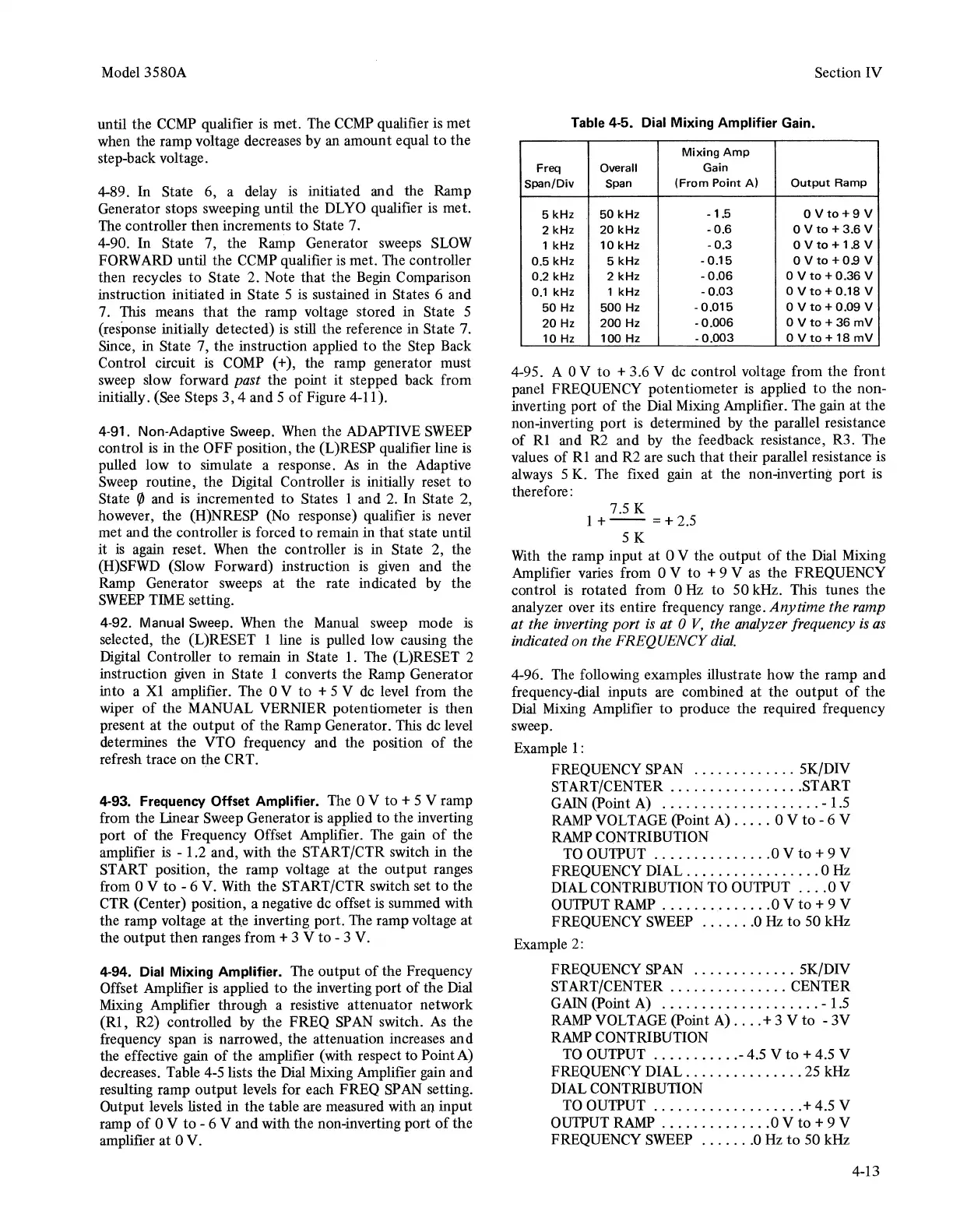
4-94. Dial Mixing Amplifier. The
output
of
the Frequency
Offset Amplifier is applied
to
the inverting port
of
the Dial
Mixing Amplifier through a resistive attenuator network
(Rl,
R2) controlled by the FREQ
SP
AN
switch.
As
the
frequency span is narrowed, the attenuation increases and
the effective gain
of
the
amplifier (with respect
to
Point A)
decreases. Table
4-S
lists the Dial Mixing Amplifier gain and
resulting ramp
output
levels for each FREQ
SP
AN
setting.
Output levels listed in the table are measured with an input
ramp
of
0 V
to
- 6 V and with the non-inverting port
of
the
amplifier at 0 V.
Section IV
Table
4-5. Dial Mixing Amplifier Gain.
Mixing
Amp
Freq Overall
Gain
Span/Div Span
(From Point
A)
Output
Ramp
5 kHz
50
kHz
-1.5
0Vto+9V
2 kHz
20
kHz
-0.6
0 V
to
+3.6
V
1 kHz
10
kHz
-0.3
0Vto+1.8V
0.5 kHz 5 kHz
-0.15
O V
to+
0.9 V
0.2 kHz
2
kHz
-0.06
0 V
to
+0.36
V
0.1
kHz
1
kHz
-0.03
0Vto+0.18V
50
Hz 500 Hz
-0.015
0
Vto
+ 0.09 V
20
Hz
200
Hz
-0.006
0
Vto
+36
mV
10
Hz
100
Hz
-0.003
0Vto+18
mV
4-9S. A 0 V
to
+ 3.6 V de control voltage from the front
panel FREQUENCY potentiometer
is
applied
to
the non-
inverting port
of
the Dial Mixing Amplifier. The gain at
the
non-inverting port
is
determined by the parallel resistance
of
Rl
and R2 and by the feedback resistance, R3. The
values
of
Rl
and R2 are such
that
their parallel resistance is
always S K. The fixed gain at the non-inverting
port
is
therefore:
7.5 K
1
+--
=+2.5
SK
With the ramp input at 0 V the output
of
the
Dial Mixing
Amplifier varies from 0 V
to
+ 9 V
as
the FREQUENCY
control
is
rotated from 0
Hz
to
SO
kHz. This tunes the
analyzer over its entire frequency range.
Anytime
the ramp
at the inverting port
is
at
0
V,
the analyzer frequency
is
as
indicated on the FREQUENCY
dial.
4-96. The following examples illustrate
how
the ramp and
frequency-dial inputs are combined at the
output
of
the
Dial Mixing Amplifier
to
produce the required frequency
sweep.
Example 1:
FREQUENCY SPAN
.............
SK/DIV
START/CENTER
................
.START
GAIN (Point A)
....................
- 1.5
RAMP
VOLTAGE (Point A)
.....
0 V
to
- 6 V
RAMP
CONTRIBUTION
TOOU1PUT
...............
0Vto+9V
FREQUENCY DIAL
.................
0
Hz
DIAL CONTRIBUTION TO OU1PUT
....
0 V
OU1PUT RAMP
..............
0 V
to+
9 V
FREQUENCY
SWEEP
.......
0
Hz
to
SO
kHz
Example 2:
FREQUENCY
SP
AN
.............
SK/DIV
START/CENTER
...............
CENTER
GAIN (Point A)
....................
- 1.5
RAMP
VOLTAGE (Point A)
....
+ 3 V
to
-3V
RAMP
CONTRIBUTION
TO
OU1PUT
...........
- 4.5 V
to
+ 4.5 V
FREQUENCY DIAL
...............
2S
kHz
DIAL CONTRIBUTION
TO
OU1PUT
...................
+ 4.S V
OU1PUT RAMP
..............
0 V
to+
9 V
FREQUENCY SWEEP
.......
0 Hz
to
SO
kHz
4-13