Model 3580A
Section IV
CLK
C9
SFL+TRA
8 BITS STORE B BITS
DY
T0+4.75Y
VIDEO
(FROM
VIDEO
OUTPUT
CIRCUITS)
MULTIPLEXER
....._,..~----------------------,
,-WRITE
CONTROL-
CLEAR
NORMAL
SFL+TRA
(H)
WRITE
ENABLE
CLK CID
(WHEN
Q' OUTPUT
OF
WRITE
CONTROL
FLIP
FLOP
IS
HIGH
l
CLK
CID
NC
/sFL
CLK
C9
SETS
FLIP
FLDP
WHEN
SFL
INSTRUCTION
IS
NOT
GIVEN
READ/WRITE
DATA
RAM
DATA
8 BITS
INPUT
(1024X8)
OUTPUT
ADDRESS
10
B
CLK Cl
I
T
WRITE
s
READ
CLOCK
10
BITS
ADDRESS
10
BITS
ADORE
SS
MULTIPLEXER
COUNTER
CARRY
CLK
C9
8-BIT
LATCH
TO
8 BITS
Q D TO A
L--t-----""\o"""
CONVERTER
SFL
+TRA
SFH
BLANK
STORE
CLEAR
CLK
Cl I
SFH
CLK
Cl
SFL+TRA
HORIZONTAL
----------------SYNC
J..--11.•m•
----lL
(TO
DISPLAY
f-11.us---J
CLKCI~
CLKC9__jL_
CLKCIO
___n__
CLKCIO
---i_r-
CLK
Cl
I
___
__,ll_
SFL
SFH
TRA
CLOCK
STORE
FUNCTION
CONTROLLER
STORE
RAMP
GENERATOR
l
SFH~(Hl
FAST
/ (TO DISPLAY
DOUBLES
DISPLAY
GEN~~~~OR
l
SWEEP RATE
WHEN
SFH
INSTRUCTION
IS
GIVEN
3580A-C-3573
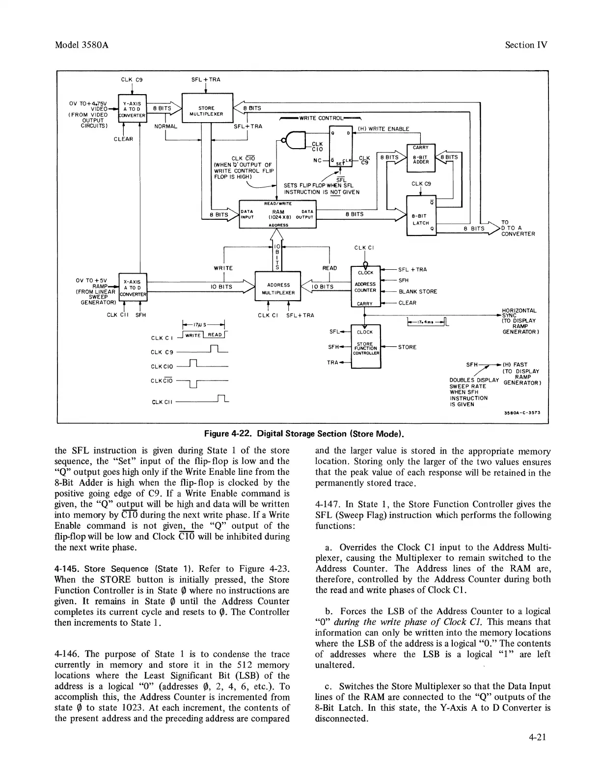
Figure 4-22. Digital Storage Section (Store Mode).
the SFL instruction
is
given
during State 1
of
the store
sequence, the
"Set"
input
of
the flip-flop
is
low and the
"Q"
output goes high only
if
the Write Enable line from the
8-Bit Adder
is
high when the flip- flop is clocked by the
positive going edge
of
C9.
If
a Write Enable command
is
given, the
"Q"
output
will
be
high and data will
be
written
into memory by ClO during the next write phase.
If
a Write
Enable command
is
not
given, the
"Q"
output
of
the
flip"flop will be low and Clock C
10
will
be inhibited during
the next write phase.
4-145. Store Sequence (State 1). Refer to Figure 4-23.
When
the STORE button
is
initially pressed, the Store
Function Controller is in State
(/J
where no instructions are
given.
It
remains in State
(/J
until the Address Counter
completes its current cycle and resets to
(/J.
The Controller
then increments
to
State 1.
4-146. The purpose
of
State 1
is
to condense the trace
currently in memory and store
it
in the 512 memory
locations where the Least Significant Bit (LSB)
of
the
address is a logical "O" (addresses
(/J,
2, 4, 6, etc.). To
accomplish this, the Address Counter
is
incremented from
state
(/J
to
state 1023. At each increment, the contents
of
the present address and the preceding address are compared
and the larger value
is
stored in the appropriate memory
location. Storing only the larger
of
the two values ensures
that the peak value
of
each response
will
be retained in the
permanently stored trace.
4-14 7. In State 1, the Store Function Controller
gives
the
SFL (Sweep Flag) instruction \\hlch performs the following
functions:
a. Overrides the Clock
Cl
input
to
the Address Multi-
plexer, causing the Multiplexer
to
remain switched to the
Address Counter. The Address lines
of
the
RAM
are,
therefore, controlled by the Address Counter during
both
the read and write phases
of
Clock C
1.
b. Forces the LSB
of
the
Adclress
Counter
to
a logical
"O" during the write
phase
of
Clock Cl. This means
that
information can only
be
written into the memory locations
where the
LSB
of
the address is a logical "O." The contents
of
addresses where the
LSB
is a logical
"l"
are left
unaltered.
c. Switches the Store Multiplexer so
that
the Data Input
lines
of
the
RAM
are connected to the
"Q"
outputs
of
the
8-Bit Latch.
In
this state, the Y-Axis A
to
D Converter
is
disconnected.
4-21