Model 3580A
Section IV
.=WRITE
CONTROL====-,
D...-(_H)_W~Rl_T_E_E_N_AB_L_E~~
CLK CIO
(WHEN 'Q' OUTPUT OF
WRITE CONTROL FLIP
FLOP
IS HIGH)
CLK
CIO
NC
Q
CLK
T
/sFL
SETS
FLIP
FLOP
WHEN
SFL
INSTRUCTION IS NOTGIVEN
READ/WRITE
CLK
C9
CARRY
8-BIT
ADDER
CLKC9
DATA
RAM
DATA
INPUT
(1024XB)
OUTPUT
____
e_B_l_Ts
___
__,_/
8-BIT
LATCH
ADDRESS
CLK
CI
TO
j+-17..,s
---j
CLK
Cl
~
CLK
C9
___Jl__
CU<
CIO
__fl_____
CLKCIO---i_r--
3580A-B-
3575
10
BITS
CLOCK
CARRY
SFL+TRA
SFH
Q
BLANK
STORE
CLEAR
D
TO
A
CONVERTER
HORIZONTAL
~~~~~~~~~~~~~~~--sYNc
1--
17o4m1
:.fl
(TO
DISPLAY
RAMP
GENERATOR)
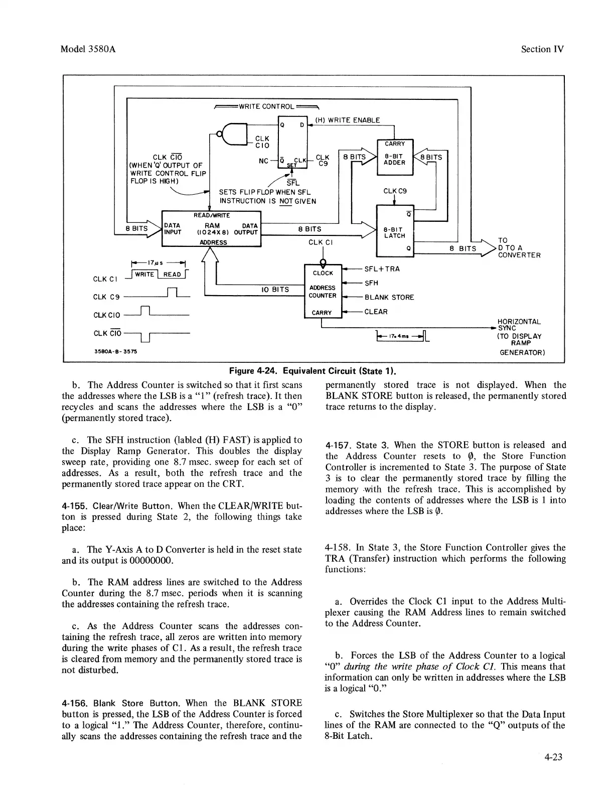
Figure 4-24. Equivalent Circuit (State 1
).
b. The Address Counter is switched
so
that
it
first scans
the addresses where the
LSB
is
a
"l"
(refresh trace).
It
then
recycles and scans the addresses where the
LSB
is a "O"
(permanently stored trace).
c. The SFH instruction (la bled (H) FAST)
is
applied
to
the Display Ramp Generator. This doubles the display
sweep rate, providing one 8.7 msec. sweep for each set
of
addresses.
As
a result,
both
the refresh trace and the
permanently stored trace appear on the CRT.
4-155. Clear/Write Button.
When
the CLEAR/WRITE but-
ton
is
pressed during State 2, the following things take
place:
a. The Y-Axis A
to
D Converter is held in the reset state
and its output is 00000000.
b. The
RAM
address lines are switched
to
the Address
Counter during the 8.7 msec. periods when
it
is
scanning
the addresses containing the refresh trace.
c.
As
the Address Counter scans the addresses con-
taining the refresh trace,
all
zeros are written into memory
during the write phases
of
Cl.
As
a result, the refresh trace
is cleared from memory and the permanently stored trace is
not disturbed.
4-156.
Blank
Store Button.
When
the BLANK STORE
button
is
pressed, the
LSB
of
the Address Counter
is
forced
to
a logical "1." The Address Counter, therefore, continu-
ally scans the addresses containing the refresh trace and the
permanently stored trace
is
not
displayed.
When
the
BLANK STORE button
is
released, the permanently stored
trace returns to the display.
4-157. State 3.
When
the STORE
button
is released and
the Address Counter resets to
</J,
the Store Function
Controller
is
incremented
to
State 3. The purpose
of
State
3 is to clear the permanently stored trace by filling the
memory
-with
the refresh trace. This
is
accomplished by
loading the contents
of
addresses where the
LSB
is 1 into
addresses where the
LSB
is
<fJ.
4-158. In State 3, the Store Function Controller
gives
the
TRA (Transfer) instruction which performs the following
functions:
a. Overrides the Clock Cl input
to
the Address Multi-
plexer causing the
RAM
Address lines to remain switched
to
the Address Counter.
b. Forces the
LSB
of
the Address Counter
to
a logical
"O" during the write phase
of
Clock Cl. This means
that
information can only be written in addresses where the
LSB
is a logical "O."
c. Switches the Store Multiplexer so that the Data Input
lines
of
the
RAM
are connected
to
the
"Q"
outputs
of
the
8-Bit Latch.
4-23