Model
3580A
PERFORMANCE
TESTS
Section V
DISPLAY
...............
CLEAR WRITE
c. Adjust the ZERO CAL control for a peak display at
the leftmost graticule
of
the CRT. Reposition the following
front panel control:
SWEEP
MODE
.................
MANUAL
d.
Adjust the frequency synthesizer for a 60 Hz,
+5
dBm
900 n output
(+
17.55 dBm/50 ohms). Connect
the synthesizer (properly terminated)
to
the INPUT
of
the
3580A.
e.
Slowly adjust MANUAL VERNIER
to
the
60
Hz
signal
which will appear
as
a peak on the sixth major
division from the left. Momentarily press the following
front panel control:
DISPLAY
...............
CLEAR
WRITE
f.
Adjust the VERNIER (Amplitude) for a
full
scale
0
dB
display.
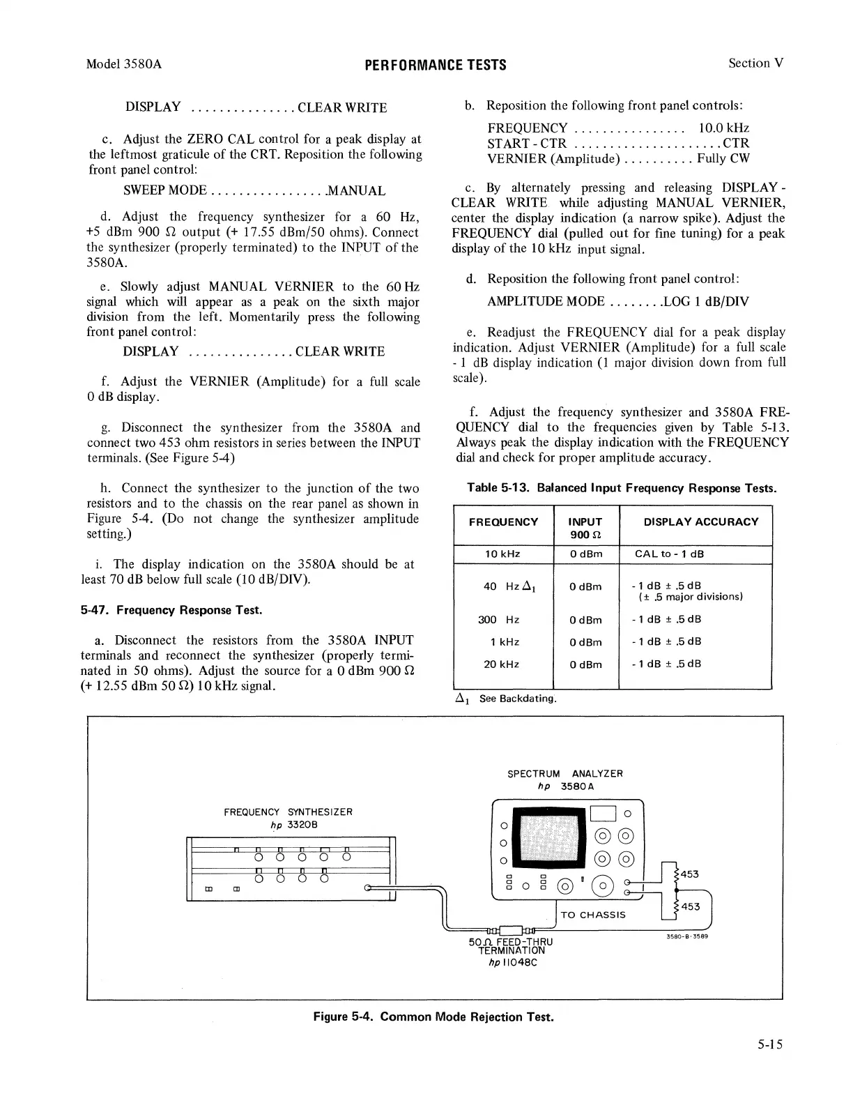
g.
Disconnect the synthesizer from the 3580A and
connect two 453 ohm resistors in series between the INPUT
terminals. (See Figure 5-4)
h. Connect the synthesizer to the junction
of
the two
resistors and to the chassis on the rear panel
as
shown in
Figure 5-4. (Do not change the synthesizer amplitude
setting.)
i.
The display indication on the 3580A should
be
at
least 70
dB
below full scale (10 dB/DN).
5-47. Frequency Response Test.
a.
Disconnect the resistors from the 3580A INPUT
terminals and reconnect the synthesizer (properly termi-
nated in 50 ohms). Adjust the source for a 0
dBm
900 n
(+
12.55
dBm
50
n)
10 kHz signal.
FREQUENCY
SYNTHESIZER
hp
33208
II
II
~
~ ~
~I
II
I!
0
I
0
0
0
tD
tD
b.
Reposition the following front panel controls:
FREQUENCY . . . . . . . . . . . . . . . . 10.0 kHz
START-CTR
.....................
CTR
VERNIER (Amplitude)
..........
Fully
CW
c.
By
alternately pressing and releasing DISPLAY -
CLEAR
WRITE
while adjusting
MANUAL
VERNIER,
center the display indication (a narrow spike). Adjust the
FREQUENCY dial (pulled out for fine tuning) for a peak
display
of
the 10 kHz input signal.
d.
Reposition the following front panel control:
AMPLITUDE
MODE
........
LOG
1 dB/DIV
e.
Readjust the FREQUENCY dial for a peak display
indication. Adjust VERNIER (Amplitude) for a full scale
- 1
dB
display indication
(1
major division down from full
scale).
f. Adjust the frequency synthesizer and 3580A FRE-
QUENCY
dial
to
the frequencies
given
by Table 5-13.
Always
peak the display indication with the FREQUENCY
dial
and check for proper amplitude accuracy.
Table 5-13. Balanced Input Frequency Response Tests.
FREQUENCY
INPUT
900.11
10
kHz
OdBm
40
Hz<!l
1
OdBm
300
Hz
OdBm
1
kHz
OdBm
20
kHz
OdBm
<!l
1
See
Backdating.
SPECTRUM ANALYZER
hp
3580A
DISPLAY ACCURACY
CALto-1dB
- 1
dB
± .5
dB
( ±
.5
major divisions)
-1
dB ±
.5dB
-1
dB
± .5
dB
-1
dB±
.5dB
0
0
0
Cl
g 0
Do
@@
@@
g@'G
50Jl
FEED-THRU
TERMINATION
hp 11048C
TO
CHASSIS
3580-8-3589
Figure
5-4. Common
Mode
Rejection Test.
5-15