52
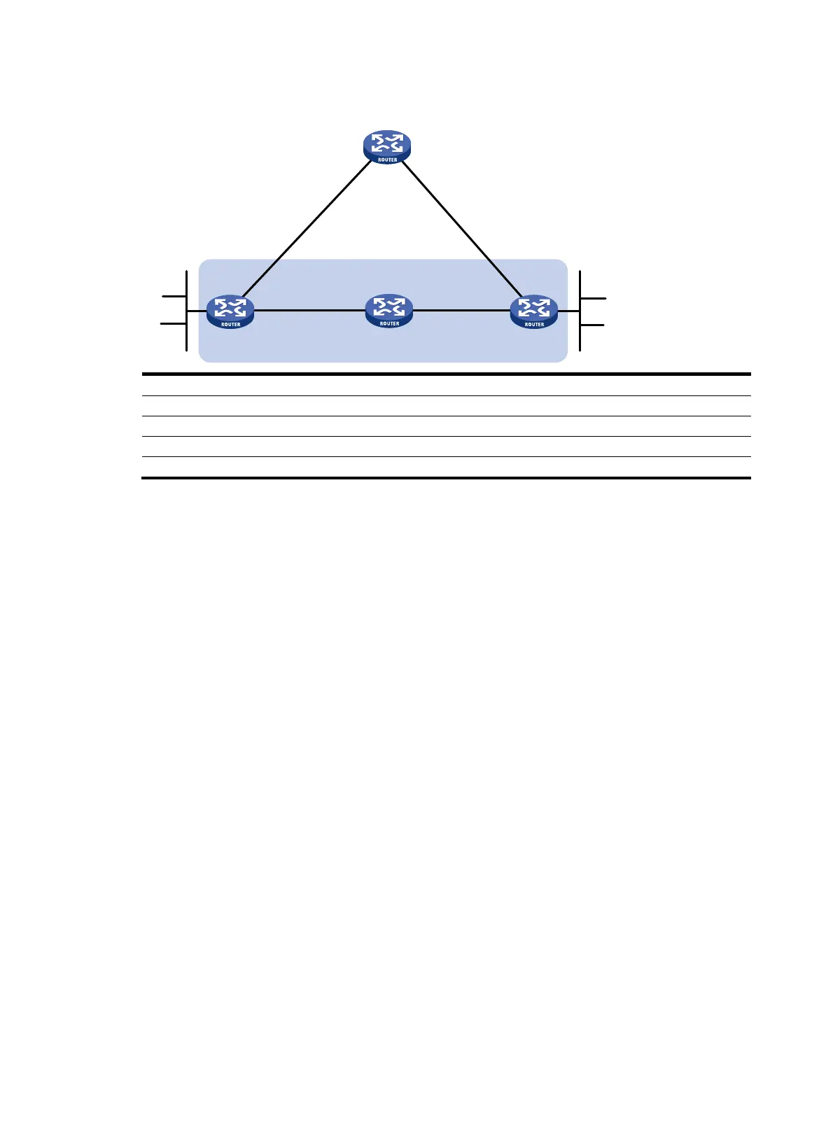
Figure 13 Network diagram
Device Interface IP address
Device
Interface
IP address
Router A Eth1/1 192.168.3.1/24 Router B Eth1/1 192.168.2.1/24
Eth1/2 192.168.1.1/24
Eth1/2
192.168.1.2/24
Router C Eth1/1 192.168.2.2/24
Router D
Eth1/1
192.168.3.2/24
Eth1/2 192.168.4.2/24 Eth1/2 192.168.4.1/24
Configuration procedure
1. Configure IP addresses for interfaces. (Details not shown.)
2. Configure basic RIP and enable static route redistribution into RIP so Router A and Router C have
routes to send to each other:
# Configure Router A.
<RouterA> system-view
[RouterA] rip 1
[RouterA-rip-1] version 2
[RouterA-rip-1] undo summary
[RouterA-rip-1] network 192.168.1.0
[RouterA-rip-1] network 101.1.1.0
[RouterA-rip-1] peer 192.168.2.2
[RouterA-rip-1] undo validate-source-address
[RouterA-rip-1] import-route static
[RouterA-rip-1] quit
[RouterA] interface ethernet 1/2
[RouterA-Ethernet1/2] rip bfd enable
[RouterA-Ethernet1/2] quit
[RouterA] rip 2
[RouterA-rip-2] version 2
[RouterA-rip-2] undo summary
[RouterA-rip-2] network 192.168.3.0
[RouterA-rip-2] quit
# Configure Router C.
<RouterC> system-view
[RouterC] rip 1
Router B
Router A
Eth1/2
Eth1/2
BFD
Eth1/1
Eth1/1
Router C
Router D
Eth1/1 Eth1/2
Eth1/2
Eth1/1
101.1.1.0/24
100.1.1.0/24

 Loading...


