Assembly
Access
4-75
• When storing the CRT, place
it
where
it
cannot
fall
or be bumped.
• The CRT envelope acts as a big capacitor when the computer
is
turned
off.
Always allow a
minute or two for the envelope to discharge before touching the anode connector.
• There
is
a bleeder resistor on the anode terminal. However,
it
is
a good idea to ground the
anode before touching
it.
Use a screwdriver to ground
it
to the Aquadag of the tube,
or
ground
it
to the chassis through a I-megohm resistor. If the screwdriver draws a fat spark, the bleeder
resistor
is
open.
Note
Leave the front bezel assembly
in
place unless
its
removal
is
required by
CRT replacement
or
replacement of the bezel
or
its
glass window.
Top Cover and Rear Cover
Remove the top cover to access any assembly
in
the display. Remove the rear cover to access the
RFI
board, graphics/digital video board, video board, CRT/yoke assembly, or fan. The top cover
must be removed to remove the rear cover.
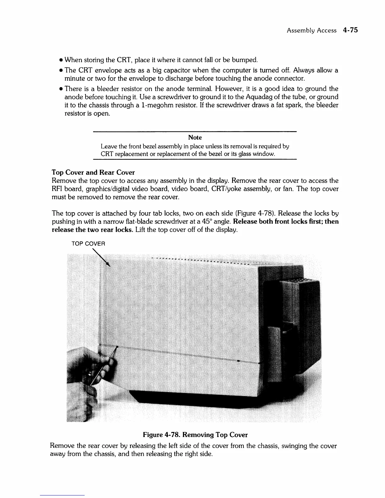
The top cover
is
attached by four tab locks, two on each side (Figure 4-78). Release the locks by
pushing
in
with a narrow flat-blade screwdriver at a 45° angle. Release both front locks first; then
release
the
two rear locks.
Lift
the top cover off of the display.
TOP COVER
Figure 4-78. Removing Top Cover
Remove the rear cover by releasing the left side of the cover from the chassis, swinging the cover
away from the chassis,
and
then releasing the right side.