EasyManuals Logo

Hypertherm Powermax30 AIR Service Manual

Hypertherm Powermax30 AIR
223 pages
To Next Page IconTo Next Page
To Previous Page IconTo Previous Page
Page #120 background imageLoading...
Page #120 background image
120 Powermax30 AIR Service Manual 808850
6 Power Supply Component Replacement
7. Slide the new control board into place, and attach it to the front panel with 3 retaining screws. Tighten the screws to
4.6 kg·cm (4 inch·pounds).
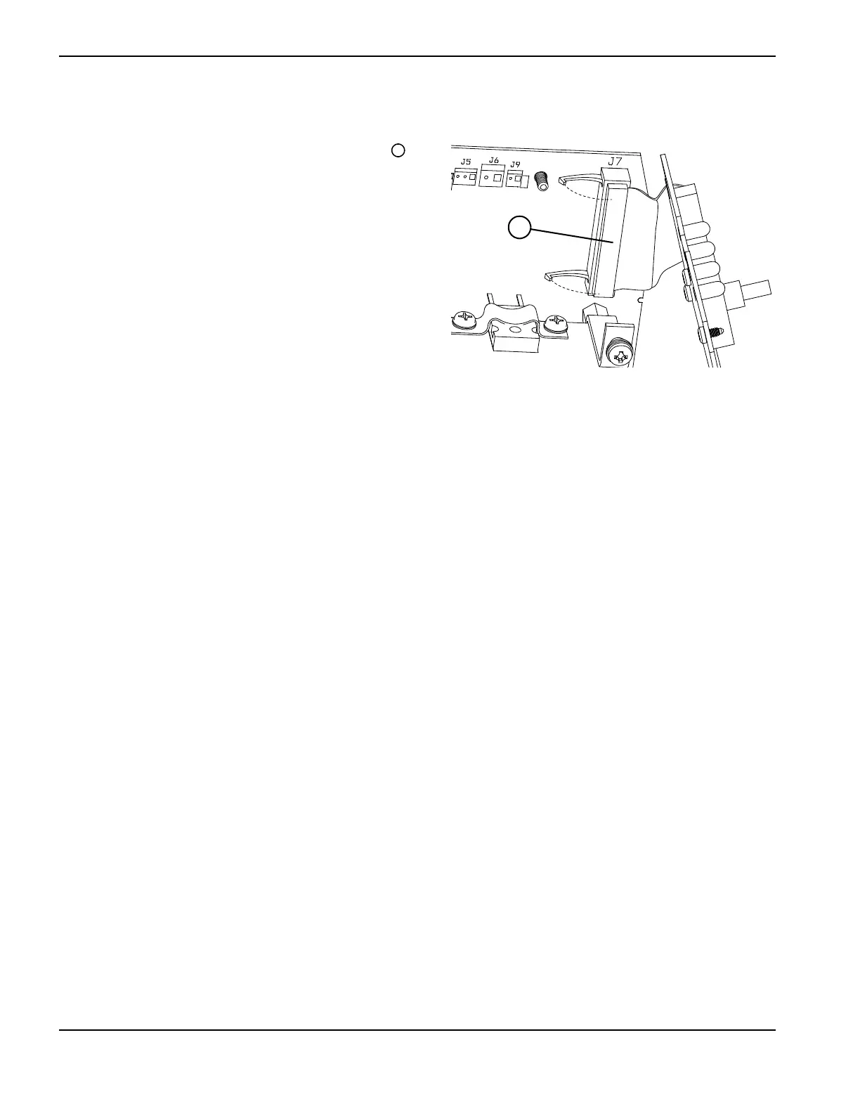
8. Connect the ribbon cable to the power board at J7 , and
fold the latches up to hold the connector in place.
9. Press the amperage adjustment knob onto the post on the
front panel of the power supply.
10. Complete the following procedures:
a. See Reattach the front panel on page 103.
b. See Install the component barrier on page 101.
c. See Install the power supply cover on page 99.
d. Reconnect the power cord, and set the power switch to
ON (I).
5
5

Table of Contents

Other manuals for Hypertherm Powermax30 AIR

Questions and Answers:

Question and Answer IconNeed help?

Do you have a question about the Hypertherm Powermax30 AIR and is the answer not in the manual?

Hypertherm Powermax30 AIR Specifications

General IconGeneral
Built-in Air CompressorYes
Output Voltage83 VDC
Input Voltage120-240 V
Current Output15–30 A
Cutting ThicknessUp to 10 mm (3/8 in) recommended cut
Gas SupplyBuilt-in air compressor
Operating Temperature-10°C to +40°C (+14°F to +104°F)

Related product manuals