124 Powermax30 AIR Service Manual 808850
6 – Power Supply Component Replacement
Install the compressor-driver board
1. Being careful not to scratch the heatsink, use a clean, soft cloth with isopropyl alcohol to remove any residual
adhesive from the top of the heatsink.
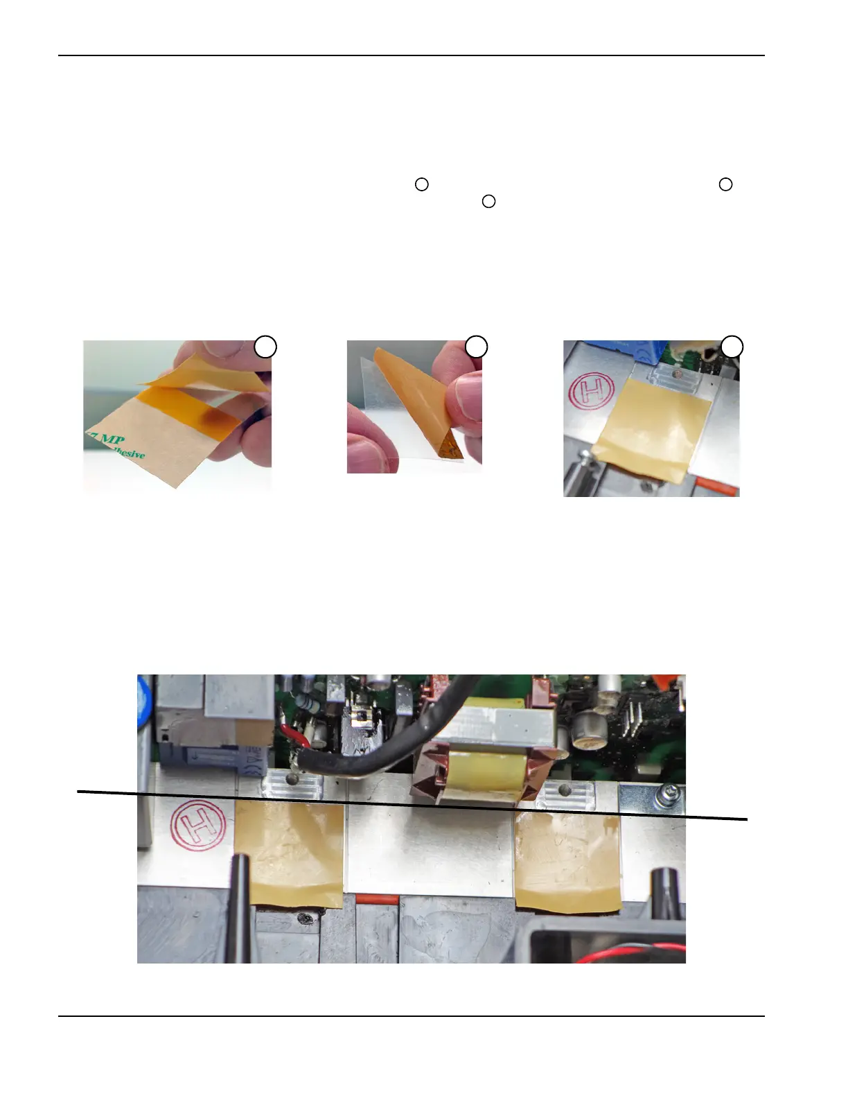
2. Remove a square thermal strip from its long backing tab . Peel the thermal strip off its clear backing sheet .
Adhere the thermal strip evenly to the heatsink where the diode sits . Make sure the strip meets the groove in the
heatsink where the clip will be attached.
If there are any creases or air bubbles in the thermal strip, remove it and apply a new one.
The kit contains additional strips.
Figure 45
3. Repeat the previous step to apply a thermal strip to the heatsink where the MOSFET sits.
4. Make sure the thermal strips line up with the grooves where the clips attach to the heatsink. The thermal strips need
to reach – or extend slightly beyond – the line shown in Figure 46.
Figure 46

 Loading...


