Powermax30 AIR Service Manual 808850 135
6 – Power Supply Component Replacement
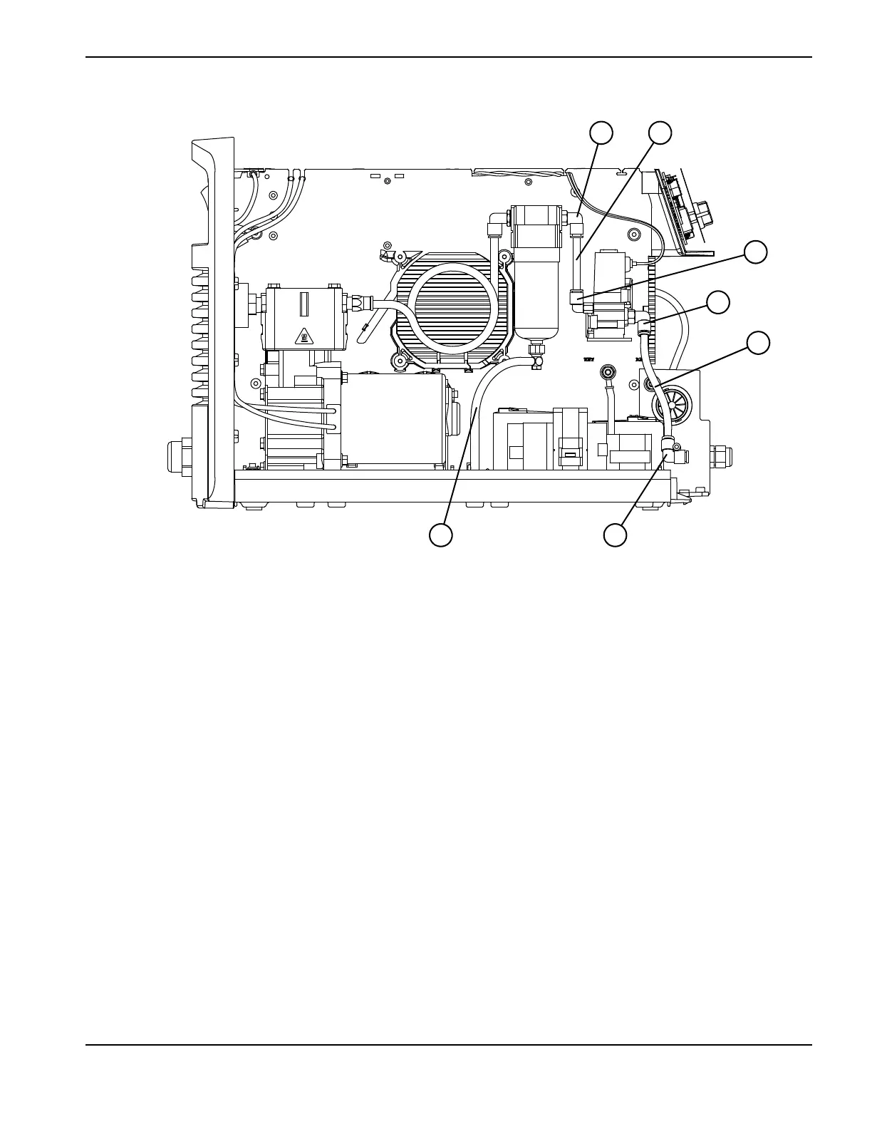
Figure 54
The fan and the front panel are hidden in Figure 54 to better show the hoses and fittings.
1 Drain hose
2 Gas hose from air filter to solenoid valve
3 90° fitting on air filter (right side)
4 90° fitting on solenoid valve (left side)
5 Gas hose from solenoid valve to torch lead
6 90° fitting for torch lead
7 90° fitting on solenoid valve (right side)

 Loading...


