172 Powermax30 AIR Service Manual 808850
6 – Power Supply Component Replacement
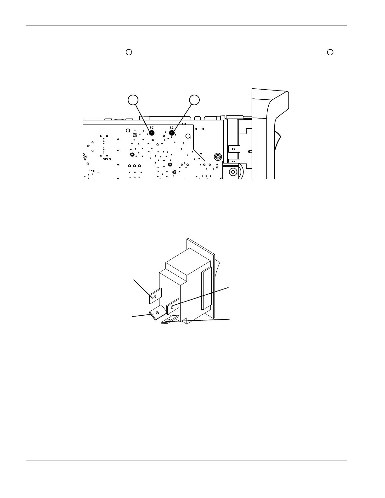
7. Push the connectors for the 2 white wires that are attached to the power board at “AC” onto the bottom 2 pins of the
power switch. The left “AC” wire connects to the bottom-left pin on the power switch; the right “AC” wire
connects to the bottom-right pin on the power switch. See Figure 83 and Figure 84.
Figure 83
8. Press the connector for the black (CSA) or brown (CE) wire onto the upper-left pin on the power switch.
9. Press the connector for the white (CSA) or blue (CE) wire onto the upper-right pin on the power switch.
Figure 84
10. Reconnect the ground wire to the ground wire clip on the rear panel.
11 . Tighten the strain relief nut on the power cord on the outside of the power supply.
12. Complete the following procedures:
a. See Install the component barrier on page 101.
b. See Install the power supply cover on page 99.
c. Reconnect the power cord, and set the power switch to ON (I).
White (AC) (bottom-left pin)
Black (CSA)
Brown (CE)
(upper-left pin)
White (AC) (bottom-right pin)
White (CSA)
Blue (CE)
(upper-right pin)