EasyManuals Logo
Home>Hypertherm>Welding System>Powermax65 SYNC

Hypertherm Powermax65 SYNC User Manual

Hypertherm Powermax65 SYNC
136 pages
To Next Page IconTo Next Page
To Previous Page IconTo Previous Page
Page #102 background imageLoading...
Page #102 background image
Service Procedures for the PCBs and Related Components
5
102 810440 Service Parts and Procedures Powermax65/85 SYNC
8. Carefully connect the following wire connectors to the power PCB. Make sure that you do not
bend or damage the connectors.
All models: Connect the gate drive wires at J19 and J18.
CSA models: Connect the gate drive wire at J17 and the PFC temperature sensor at J16.
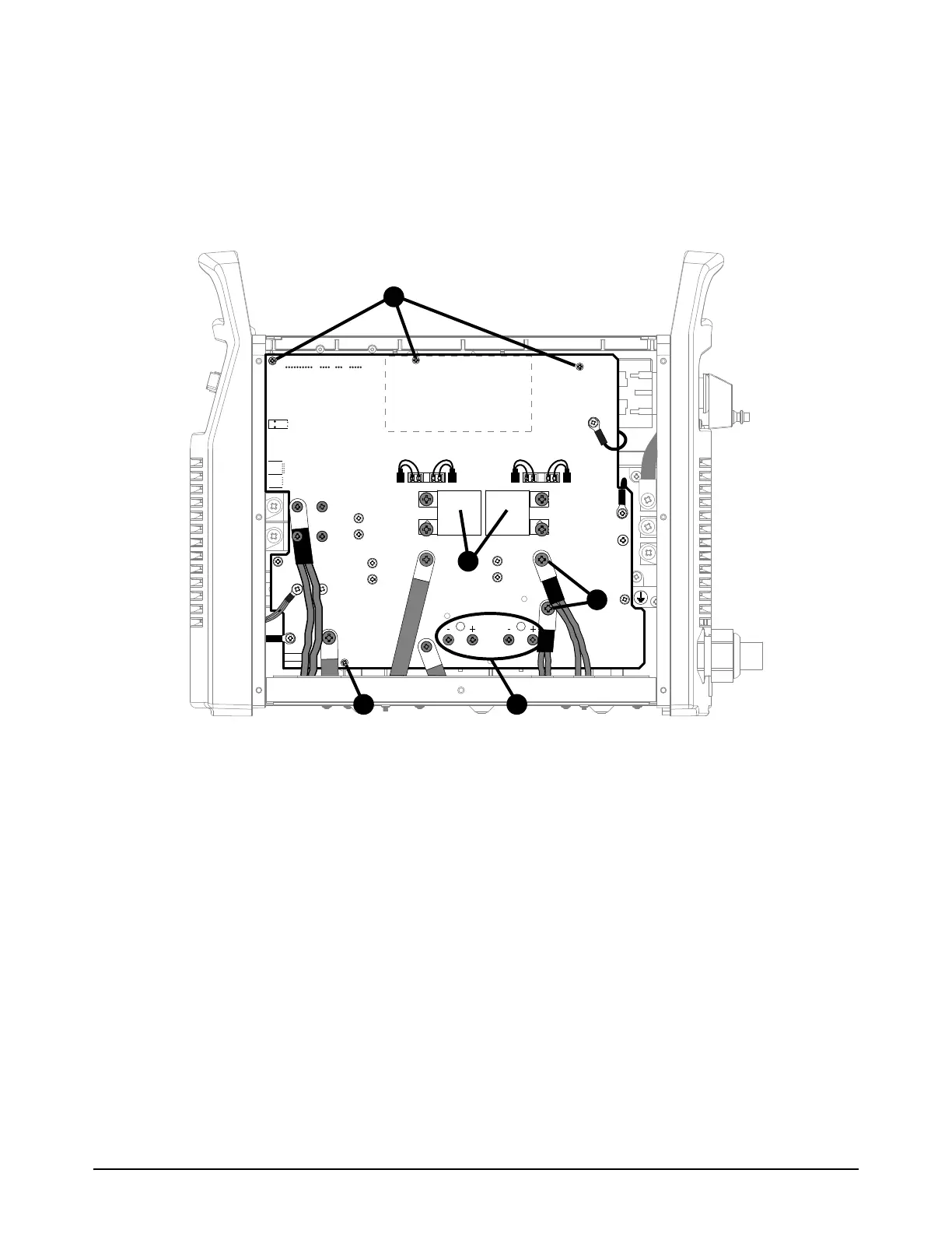
Figure 3 – Powermax65/85 SYNC CSA power PCB
RED
J32
RED
J21
ORG
J20
J12
B
R
WORK
LEAD
BLK
BLK
J13
J16J17J18J19
J26
J29
TP12
J28
TP10
TP11
W
R
B
J4 J2 J1J3
1
5
6
6
2

Table of Contents

Other manuals for Hypertherm Powermax65 SYNC

Questions and Answers:

Question and Answer IconNeed help?

Do you have a question about the Hypertherm Powermax65 SYNC and is the answer not in the manual?

Hypertherm Powermax65 SYNC Specifications

General IconGeneral
BrandHypertherm
ModelPowermax65 SYNC
CategoryWelding System
LanguageEnglish

Related product manuals