Service Procedures for the PCBs and Related Components
Powermax65/85 SYNC Service Parts and Procedures 810440 11 9
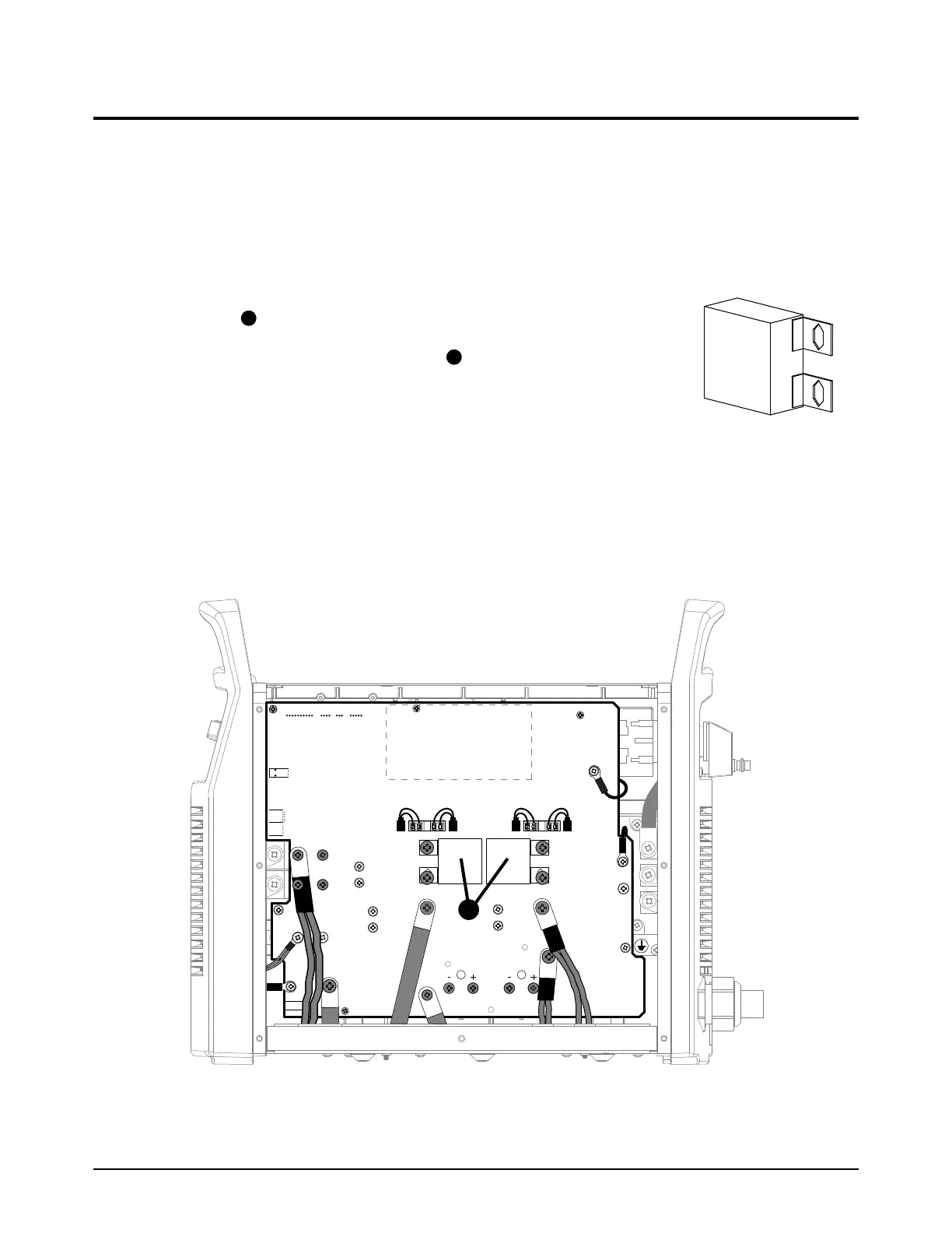
Replace the power PCB capacitors
For kit contents, refer to Plasma power supply interior, power PCB side on page 26.
1. Set the plasma power supply switch to OFF (O), disconnect the power cord from the power
source, and disconnect the gas supply.
2. Remove the plasma power supply cover and the component barrier. Refer to page 49.
3. From the power PCB side, remove the 2 screws from the 3 µF
capacitor to be replaced. Refer to Figure 17 and Figure 18.
4. Attach the new power PCB capacitor to the power PCB with
the 2 mounting screws.
65 A CSA models: Use the M5 screws (075570) in the kit.
65 A CE/CCC models and all 85 A models: Use the
M6 screws (075569) in the kit.
Tighten the screws to 4.0 N·m (35 lbf·in).
5. Install the component barrier and plasma power supply cover. Refer to page 51.
Figure 17 – Capacitors in CSA models
RED
J32
RED
J21
ORG
J20
J12
B
R
WORK
LEAD
BLK
BLK
J13
J16J17J18J19
J26
J29
TP12
J28
TP10
TP11
W
R
B
J4 J2 J1J3