Service Procedures for the PCBs and Related Components
96 810440 Service Parts and Procedures Powermax65/85 SYNC
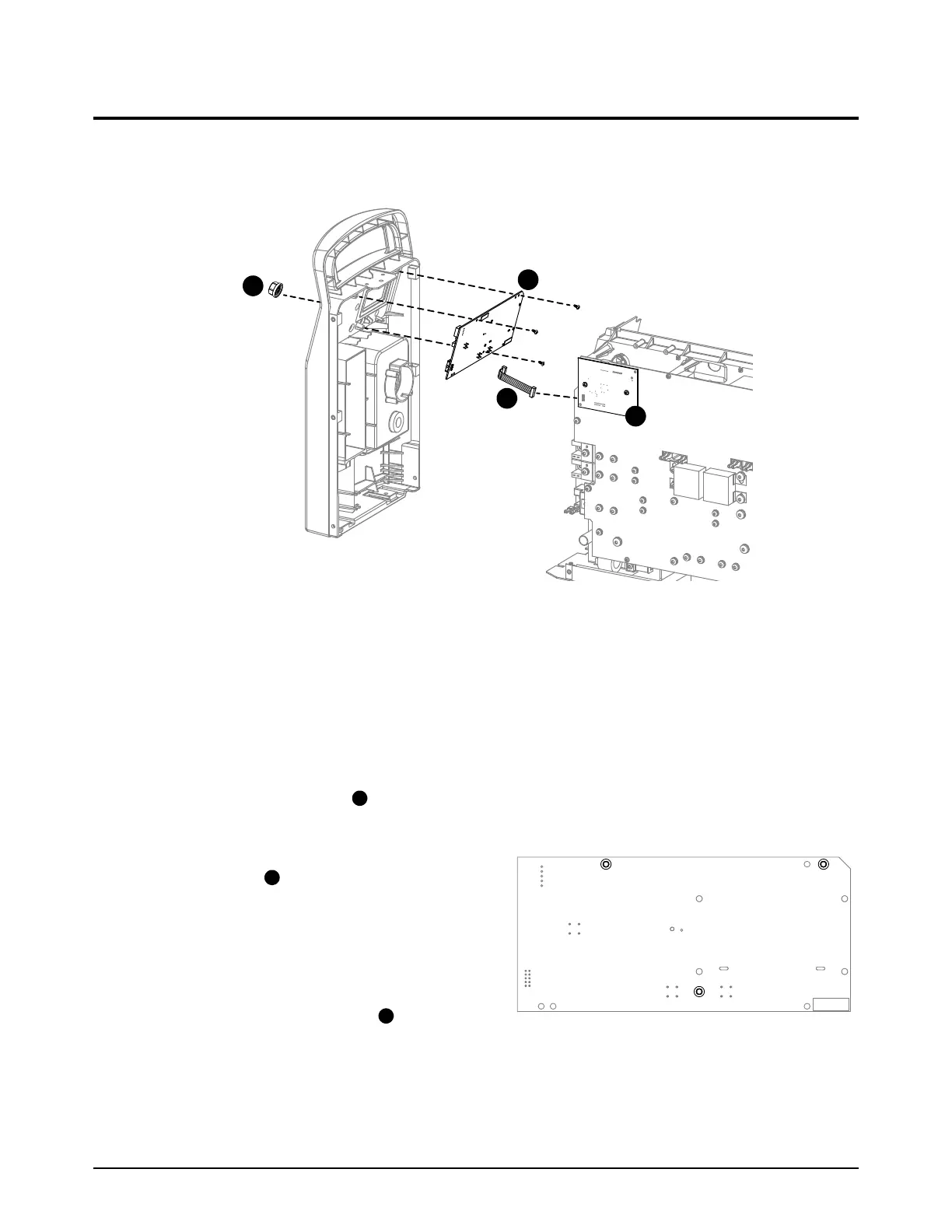
Replace the control PCB and the ribbon cable
For kit contents, refer to Plasma power supply interior, front on page 24. The control PCB and the
ribbon cable are sold as different kits. The control PCB does not come with a ribbon cable.
Remove the control PCB and the ribbon cable
1. Set the power switch on the plasma power supply to OFF (O), disconnect the power cord, and
disconnect the gas supply.
2. Remove the plasma power supply cover and the component barrier. Refer to page 49.
3. Loosen the front panel. Refer to page 55.
4. Pull the adjustment knob off of its post on the front panel. If necessary, use a blade
screwdriver to carefully pry the knob off of the post.
5. Remove the 3 mounting screws from the
control PCB . Use an offset TORX
screwdriver. The screws have the label MTG.
6. From the power PCB side of the plasma
power supply, remove the control PCB from
the front panel.
7. Disconnect the ribbon cable from J6 on
the control PCB.
MTG