Service Procedures for the PCBs and Related Components
11 4 810440 Service Parts and Procedures Powermax65/85 SYNC
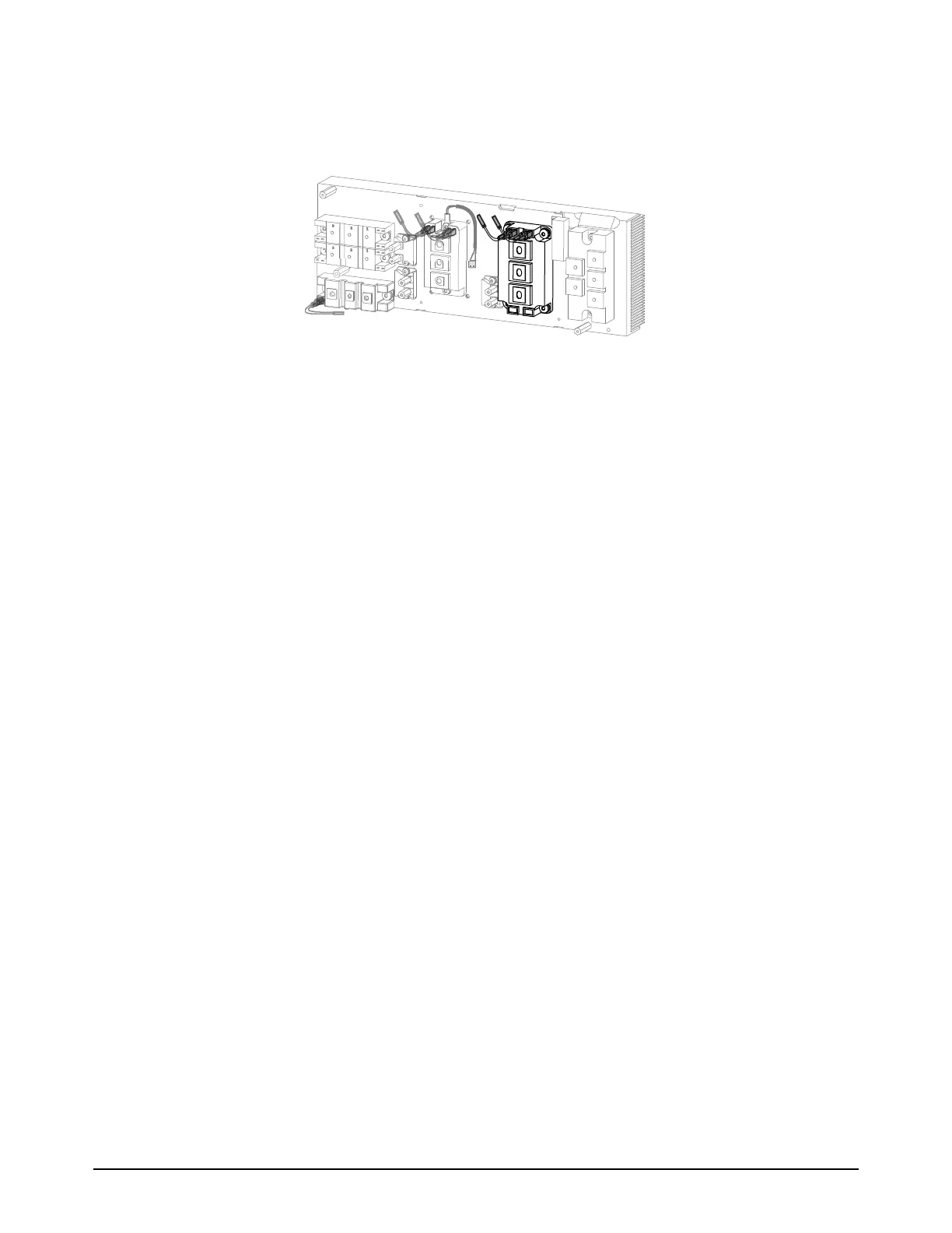
Replace the PFC IGBT
Figure 13 — PFC IGBT on heatsink
1. Set the plasma power supply switch to OFF (O), disconnect the power cord from the power
source, and disconnect the gas supply.
2. Remove the power PCB. Refer to page 98. Make sure that you put the power PCB in an
anti-static bag until you are prepared to install it.
3. Remove the 4 mounting screws to remove the PFC IGBT from the heatsink.
4. Correctly clean the heatsink and apply thermal grease to the new component before you
install it. Refer to How to clean the heatsink and apply thermal grease to the heatsink
components on page 118.
5. Position the new PFC IGBT correctly. Refer to Figure 14.
6. Attach the PFC IGBT to the heatsink with the 4 mounting screws. Tighten the screws to
4.0 N·m (35 lbf·in).
7. If there is too much thermal grease around the edges of the new component, carefully remove it.
Make sure that the heatsink is clean.
8. Connect the new gate drive wires to the terminals on the PFC IGBT with the correct polarity, as
follows. Do not use the old gate drive wires on the new PFC IGBT.
a. For the gate wires on the left, connect the black wire to the left terminal (G2) and the red
wire to the right terminal (E2).
b. For the gate drive wires on the right, connect the black wire to the left terminal (E1) and the
red wire to the right terminal (G1).
c. Make sure that the gate drive wire connectors are fully installed on the terminals. Use needle
nose pliers if necessary to install them correctly.
9. Install the power PCB. Refer to page 98.