Service Procedures for the PCBs and Related Components
Powermax65/85 SYNC Service Parts and Procedures 810440 11 3
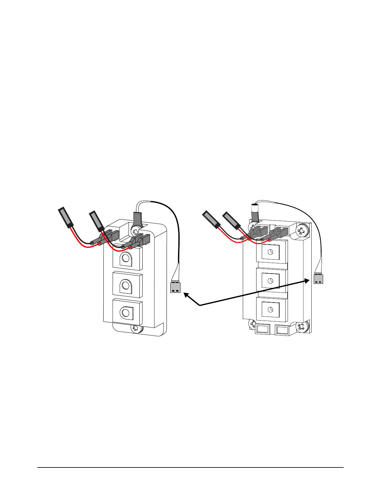
7. Connect the new gate drive wires to the terminals on the inverter IGBT with the correct polarity,
as follows. Do not use the old gate drive wires on the new inverter IGBT.
a. For the gate wires on the left, connect the black wire to the left terminal (6 or G2) and the
red wire to the right terminal (7 or E2).
b. For the gate drive wires on the right, connect the black wire to the left terminal (5 or E1) and
the red wire to the right terminal (4 or G1).
c. Make sure that the gate drive wire connectors are fully installed on the terminals. Use needle
nose pliers if necessary to install them correctly.
8. If there is too much thermal grease around the edges of the new component, carefully remove it.
Make sure that the heatsink is clean.
9. Install the power PCB. Refer to page 98.
Figure 12
Black wires on left terminals.
Red wires on right terminals.
Thermal sensor
65 A CSA 65 A CE/CCC, 85 A CSA/CE/CCC