Service Procedures for the Cover, Panels, and Connectors
Powermax65/85 SYNC Service Parts and Procedures 810440 59
Replace the front panel
For kit contents, refer to Front panel on page 25.
Remove the front panel
1. Set the plasma power supply switch to OFF (O), disconnect the power cord from the power
source, and disconnect the gas supply.
2. Loosen the front panel. Refer to page 55.
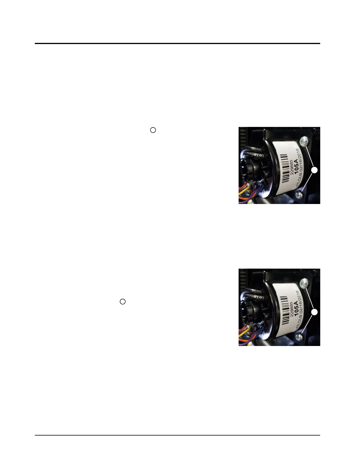
3. Remove the 4 mounting screws from the torch
quick-disconnect receptacle housing.
4. Remove the torch quick-disconnect receptacle housing from the
front panel.
5. Remove the work lead receptacle. Refer to page 69.
6. Remove the control PCB and disconnect the ribbon cable.
Refer to page 96.
7. Remove the front panel from the plasma power supply.
Install the front panel
1. Push the front panel onto the body of the plasma power supply.
2. Install the control PCB and ribbon cable. Refer to page 97.
3. Install the work lead receptacle. Refer to page 70.
4. Attach the torch quick-disconnect receptacle to the inside of
the front panel with the 4 mounting screws. Tighten the screws
to 1.7N·m (15lbf·in) .
5. Attach the front panel. Refer to page 56.
6. Install the plasma power supply cover and the component
barrier. Refer to page 51.