Service Procedures for the Cover, Panels, and Connectors
76 810440 Service Parts and Procedures Powermax65/85 SYNC
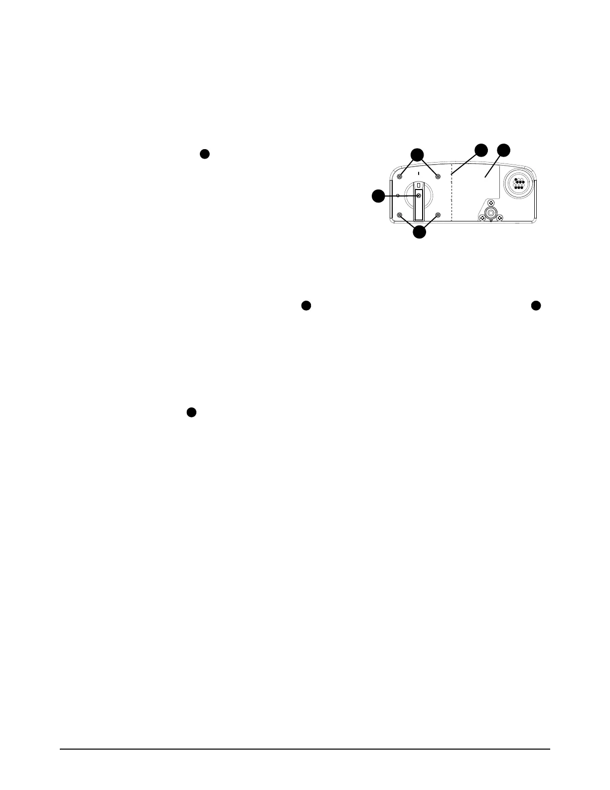
Install the power switch
1. Put the power switch into the plasma power supply.
2. Push the power switch post through the hole in the rear panel.
3. Attach the power switch to the rear panel with the
4 mounting screws . Tighten the screws to 1.7 Nm
(15 lbfin).
4. If the optional RS-485 receptacle is not installed:
a. Peel the protective cover off the new label.
b. Carefully align the hole in the label with the correct
hole in the rear panel.
c. Push the label onto the rear panel.
5. If the optional RS-485 receptacle is installed:
a. Bend the new label at the perforation and tear the label in half. Discard the right half .
b. Peel the protective cover off the left half of the new label.
c. Carefully align the hole in the label with the correct hole in the rear panel.
d. Push the label onto the rear panel.
6. Put the power switch handle onto the post.
7. Install the screw into the power switch handle. Tighten the screw to 0.8 Nm (7 lbfin).
6 BAR (85 PSI) MIN
9 BAR (135 PSI) MAX