Service Procedures for the Cover, Panels, and Connectors
Powermax65/85 SYNC Service Parts and Procedures 810440 77
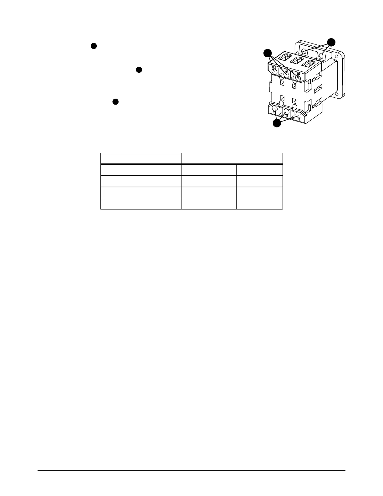
8. Put the auxiliary wires in the auxiliary switch. Tighten the
screws to 1.1 Nm (10 lbfin).
9. Put the AC input wires into the bottom of the power switch.
Tighten the set screws to 2.3 Nm (20 lbfin) for CSA models
or 0.8 Nm (7 lbfin) for CE/CCC models.
10. Put the 3 power wires into the top of the power switch. Tighten
the set screws to 2.3 Nm (20 lbfin) for CSA models or
0.8 Nm (7 lbfin) for CE/CCC models.
Table 1
11 . Attach the rear panel. Refer to page 58.
12. Install the plasma power supply cover and the component barrier. Refer to page 51.
Color
Power Wire Position CSA CE/CCC
L1 Black Brown
L2 White Black
L3 Red Grey