Service Procedures for the PCBs and Related Components
Powermax65/85 SYNC Service Parts and Procedures 810440 97
8. Is it necessary to replace the ribbon cable?
If yes, go to the next step.
If no, continue with Install the control PCB and the ribbon cable.
9. Remove the left mounting screw from the DSP PCB .
10. Disconnect the ribbon cable from J6 on the DSP PCB.
Install the control PCB and the ribbon cable
1. Connect the ribbon cable to the J6 connector on the new control PCB .
2. From the power PCB side of the plasma power supply, put the control PCB into position in the
front panel as follows:
a. Tilt the bottom of the control PCB towards the front panel until it is on the plastic tabs in the
panel.
b. Push the post on the control PCB through the hole in the front panel.
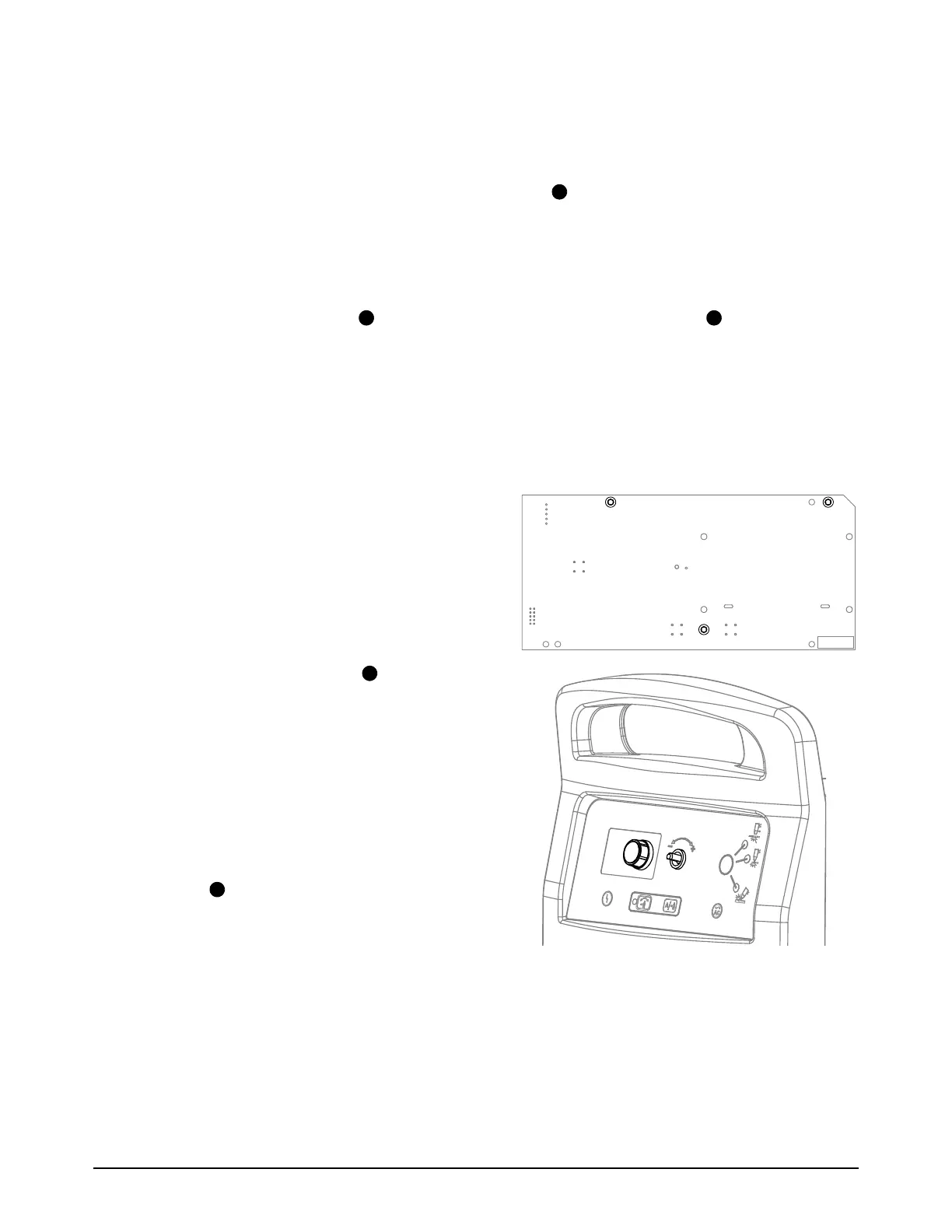
3. Attach the control PCB to the front panel
with the 3 mounting screws. Tighten the
screws to 0.6 N·m (5 lbf·in).
4. Push the adjustment knob onto the post
in the front panel.
5. Attach the front panel. Refer to page 56.
6. Did you install a new ribbon cable?
If yes, go to the next step.
If no, continue with step 9.
7. Connect the ribbon cable to J6 on the DSB
PCB .
8. Install the left mounting screw in the DSP
PCB. Tighten the screw to 1.1 N·m (10 lbf·in).
9. Install the component barrier and the plasma power supply cover. Refer to page 51.
MTG