Service Procedures for the PCBs and Related Components
104 810440 Service Parts and Procedures Powermax65/85 SYNC
10. Install the DSP PCB, as follows:
a. Connect the ribbon cable to J6 on the DSP PCB.
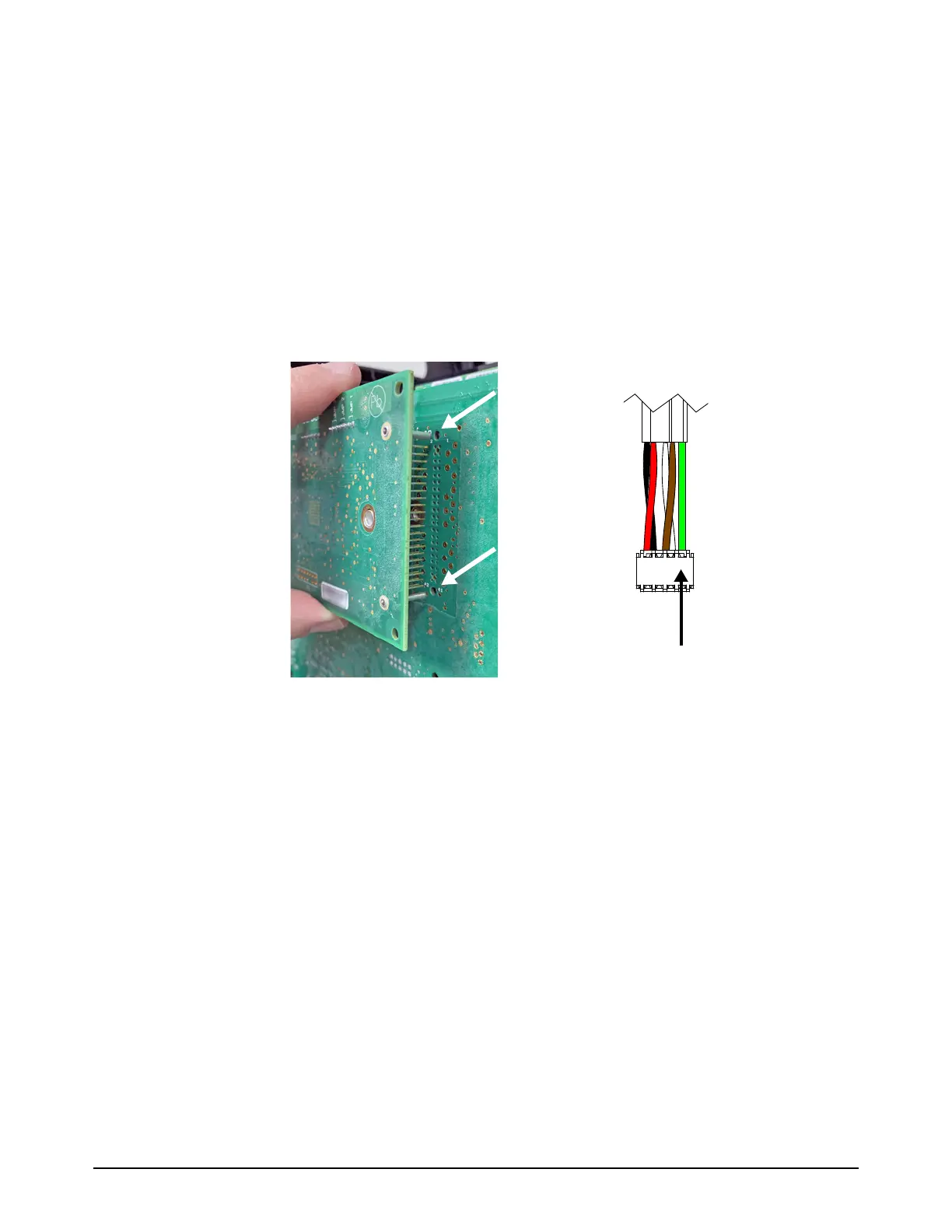
b. Align the 2 posts with the related holes in the power PCB.
c. Carefully push the DSP PCB onto the power PCB. Do not bend the pins.
d. Attach the DSP PCB to the power PCB with the 2 mounting screws. Tighten the screws to
1.1N·m (10lbf·in).
e. If there is an RS-485 serial communication PCB installed, connect the DSP connector to J7
at the top of the DSP PCB.
Make sure that the connector is in the correct position. The green wire (pin 1) must be at the
right.
11 . Make sure that all of the wires are correctly attached to the power PCB. Refer to the picture
from step 4 on page 98.
12. Make sure that all of the screws on the power PCB are fully tightened.
13. Install the end panel bracket. Refer to page 54.
14. Install the plasma supply cover and component barrier. Refer to page 51.