Service Procedures for the Magnetics
Powermax65/85 SYNC Service Parts and Procedures 810440 129
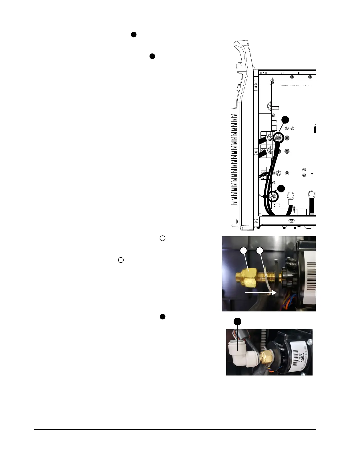
5. Attach the electrode wire to the power PCB. Tighten
the screw to 2.3 Nm (20 lbfin).
6. Attach the output inductor wires to the power PCB.
Tighten the screw to 2.3 Nm (20 lbfin).
7. Put the output inductor ring terminal over the torch
quick-disconnect receptacle.
8. Put the retention nut onto the torch quick-disconnect
receptacle. Tighten the nut to 46.1 kgcm (40 lbfin).
9. Push-to-connect the 90° gas fitting onto the torch
quick-disconnect receptacle.
10. Attach the front panel. Refer to page 56.
11 . Install the end panel bracket. Refer to page 54.
12. Install the component barrier and the plasma power supply
cover. Refer to page 51.