Service Procedures for the Cover, Panels, and Connectors
74 810440 Service Parts and Procedures Powermax65/85 SYNC
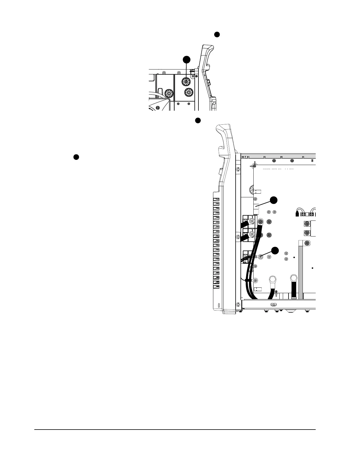
9. Put the torch interface cable through the upper grommet on the center panel.
10. From the power PCB side, attach the nozzle wires
to the power PCB. Tighten the screw to 2.3 Nm
(20 lbfin).
11 . Connect the torch interface cable connector to
J20 on the power PCB.
12. Attach the front panel. Refer to page 56.
13. Install the plasma power supply cover and the
component barrier. Refer to page 51.
RED
ORG
RED
B
R
WORK
LEAD
TP9
TP8
W
B