9: MOVE INSTRUCTIONS
9-6 OPENNET CONTROLLER USER’S MANUAL
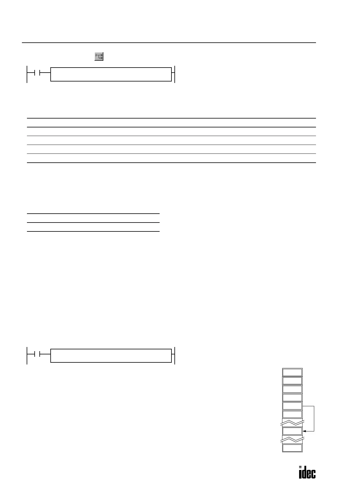
IMOV (Indirect Move)
Valid Operands
For the valid operand number range, see page 6-2.
▲ Internal relays M0 through M2557 can be designated as D1. Special internal relays cannot be designated as D1.
When T (timer) or C (counter) is used as S1, S2, or D2, the operand data is the timer/counter current value. When T (timer)
or C (counter) is used as D1, the operand data is the timer/counter preset value which can be 0 through 65535.
Valid Data Types
When a bit operand such as I (input), Q (output), M (internal relay), or R (shift register) is designated as the source S1 or
destination D1, 16 points (word data type) or 32 points (double-word data type) are used. When repeat is designated for a
bit operand, the quantity of operand bits increases in 16- or 32-point increments.
When a word operand such as T (timer), C (counter), D (data register), or L (link register) is designated as the source S1 or
destination D1, 1 point (word data type) or 2 points (double-word data type) are used. When repeat is designated for a
word operand, the quantity of operand words increases in 1- or 2-point increments.
For source operand S2 and destination operand D2, 16 points (bit operand) or 1 point (word operand) is always used with-
out regard to the data type. Source operand S2 and destination operand D2 do not have to be designated. If S2 or D2 is not
designated, the source or destination operand is determined by S1 or D1 without offset.
Make sure that the source data determined by S1 + S2 and the destination data determined by D1 + D2 are within the valid
operand range. If the derived source or destination operand is out of the valid operand range, a user program execution
error will result, turning on special internal relay M8004 and the ERROR LED on the CPU module.
Example: IMOV
Operand Function I Q M R T C D L Constant Repeat
S1 (Source 1) Base address to move from XXXXXXXX — 1-99
S2 (Source 2) Offset for S1 XXXXXXXX ——
D1 (Destination 1) Base address to move to — X ▲ XXXXX — 1-99
D2 (Destination 2) Offset for D1 XXXXXXXX ——
W (word) I (integer) D (double word) L (long)
X — X —
S1 + S2 → D1 + D2
When input is on, the values contained in operands des-
ignated by S1 and S2 are added to determine the source
of data. The 16- or 32-bit data so determined is moved to
destination, which is determined by the sum of values
contained in operands designated by D1 and D2.
REP
**
S1(R)
*****
D1(R)
*****
IMOV(*) S2
*****
D2
*****
D20 + C10 → D10 + D25
Source operand S1 and destination operand D1 determine the type of operand. Source operand S2
and destination operand D2 are the offset values to determine the source and destination operands.
If the current value of counter C10 designated by source operand S2 is 4, the source data is deter-
mined by adding the offset to data register D20 designated by source operand S1:
D(20 + 4) = D24
If data register D25 contains a value of 20, the destination is determined by adding the offset to
data register D10 designated by destination operand D1:
D(10 + 20) = D30
As a result, when input I0 is on, the data in data register D24 is moved to data register D30.
D23
D22
6450
D24
6450
D30
D21
D20
20
D25
4
C10
I0
REPS1 –
D20
D1 –
D10
IMOV(W) S2
C10
D2
D25
Phone: 800.894.0412 - Fax: 888.723.4773 - Web: www.clrwtr.com - Email: info@clrwtr.com

 Loading...

