2: MODULE SPECIFICATIONS
2-28 OPENNET CONTROLLER USER’S MANUAL
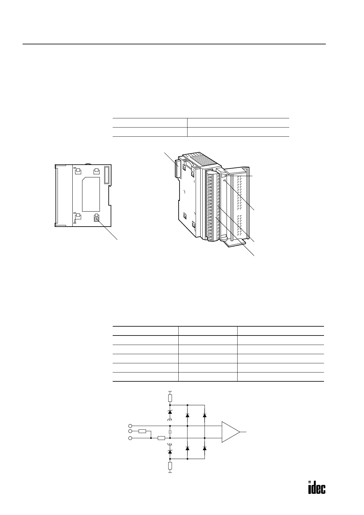
Analog Input Module (A/D Converter)
The 12-bit analog input module converts 6 channels of analog signals to digital data of 0 through 4000 which can be pro-
cessed using advanced instructions such as the coordinate conversion instruction. The analog input module is a functional
module and the converted digital data is stored to a link register, depending on the analog channel and the mounting slot
number of the analog input module in the system setup. The input mode can be selected using the rotary switch to meet
five different analog signal ranges; 0 to 10V, ±10V, 0 to 5V, ±5V, or 4 to 20 mA.
Analog Input Module Type Number
Parts Description
(1) Module ID A/D indicates the analog input module ID.
(2) Power LED Turns on when power is on.
(3) Cable Terminal Screw terminal block
(4) Terminal Label Indicates terminal numbers on the terminal block.
(5) Expansion Connector Connects to CPU and other modules.
(6) Rotary Switch Selects the input mode from five different signal ranges
Module Name 6-channel Analog Input Module
Type No. FC3A-AD1261
Rotary Switch Position Input Signal Range Resolution (Input value of LSB)
0 0 to 10V DC 2.5 mV
1 ±10V DC 5 mV
2 0 to 5V DC 1.25 mV
3 ±5V DC 2.5 mV
4 4 to 20 mA DC 4 µA
(5) Expansion Connector
(1) Module ID
(2) Power LED
(3) Cable Terminal
(4) Terminal Label
(6) Rotary Switch
Voltage Input
COM
+V
250Ω
+
–
–V
Differential
Current Input
Amplifier
ype o
ro
ec
on
Phone: 800.894.0412 - Fax: 888.723.4773 - Web: www.clrwtr.com - Email: info@clrwtr.com

 Loading...

