OPENNET CONTROLLER USER’S MANUAL 16-1
16: INTERFACE INSTRUCTIONS
Introduction
The DISP (display) instruction is used to display 1 through 5 digits of timer/counter current values and data register data
on 7-segment display units.
The DGRD (digital read) instruction is used to read 1 through 5 digits of digital switch settings to a data register. This
instruction is useful to change preset values for timers and counters using digital switches.
The CDISP (character display) instruction is used to display a maximum of 16 characters on dot matrix display units.
DISP (Display)
Valid Operands
For the valid operand number range, see page 6-2.
▲ Internal relays M0 through M2557 can be designated as Q. Special internal relays cannot be designated as Q.
When T (timer) or C (counter) is used as S1, the timer/counter current value is read out.
Conversion
BCD: To connect BCD (decimal) display units
BIN: To connect BIN (hexadecimal) display units
Latch Phase and Data Phase
Select the latch and data phases to match the phases of the display units in consideration of sink or source output of the
OpenNet Controller output module.
Output Points
The quantity of required output points is 4 plus the quantity of digits to display. When displaying 4 digits with output Q0
designated as the first output number, 8 consecutive output points must be reserved starting with Q0 through Q7.
Display Processing Time
Displaying numerical data requires the following time after the input to the DISP instruction is turned on. Keep the input
to the DISP instruction for the period of time shown below to process the display data.
When the scan time is less than 5 msec, the data cannot be displayed correctly. When the scan time is too short to ensure
normal display, set a value of 6 or more (in msec) to special data register D8022 (constant scan time preset value). See
page 5-20.
Operand Function I Q M R T C D L Constant Repeat
S1 (Source 1) Data to display ———— XXX—— —
Q (Output) First output number to display data — X ▲ ————— — —
Scan Time Display Processing Time
5 msec or more 3 scan times × Quantity of digits
Latch phase:
Low or High
Data phase:
Low or High
Conversion:
BCD or BIN
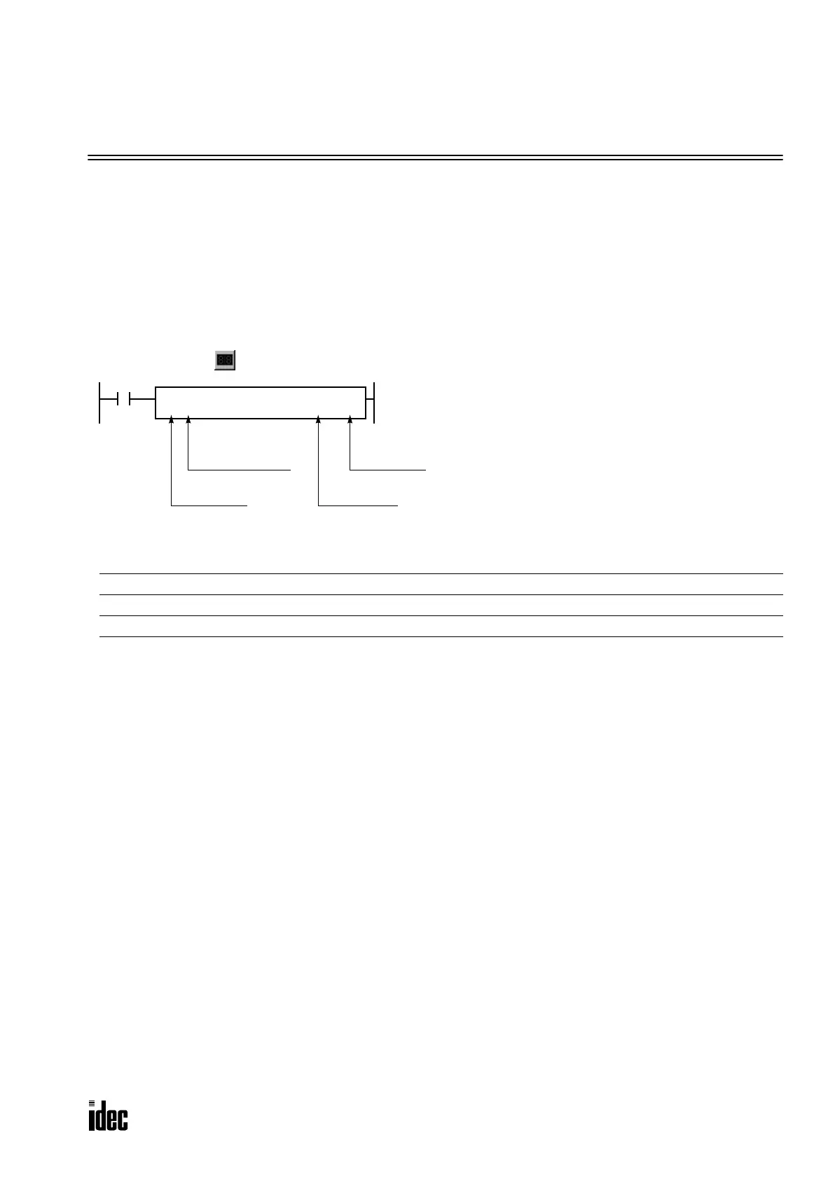
When input is on, data designated by source operand S1 is
set to outputs or internal relays designated by operand Q.
This instruction is used to output 7-segment data to display
units.
Eight DISP instructions can be used in a user program.
Display data can be 0 through 65535 (FFFFh).
Note: The DISP instruction can be used on transistor out-
put modules only.
DISP
DATS1
*****
Q
*****
BCD4
LAT
LL
Quantity of digits:
1 to 5 (decimal)
1 to 4 (hex)
Phone: 800.894.0412 - Fax: 888.723.4773 - Web: www.clrwtr.com - Email: info@clrwtr.com

 Loading...

