21: DATA LINK COMMUNICATION
OPENNET CONTROLLER USER’S MANUAL 21-11
Operating Procedure for Data Link System
To set up and use a data link system, complete the following steps:
1. From the WindLDR menu bar, select Configure > Function Area Settings. The Function Area Setting dialog box
appears.
2. First determine the assignments for the master station and slave stations.
3. Connect the OpenNet Controller CPU modules at the master station and all slave stations as illustrated on page 21-2.
4. Set communication selector DIP switch 1 to ON at all master and slave stations to select the data link mode for the
RS485 port.
5. Set communication selector DIP switches 4 through 8 to select master station number 0 and slave station numbers 1
through 31 as many as required. The slave station numbers do not have to be consecutive.
6. Create user programs for the master and slave stations. Different programs are used for the master and slave stations.
7. Using WindLDR, enter settings to Configure > Function Area Settings > Data Link for the master station. Only when
a baud rate of 38400 bps is used, enter the setting to the Data Link page in WindLDR for the slave station. For program-
ming WindLDR, see page 21-7.
8. Power up all OpenNet Controller CPU modules at the same time, and download the user programs to the master and
slave stations.
9. Monitor the data registers used for data link at the master and slave stations.
Note: To enable data link communication, power up all OpenNet Controller modules at the same time, or power up slave sta-
tions first. If a slave station is powered up later than the master station, the master station does not recognize the slave sta-
tion. To make the master station recognize the slave station in this case, turn on special internal relay M8007 (data link
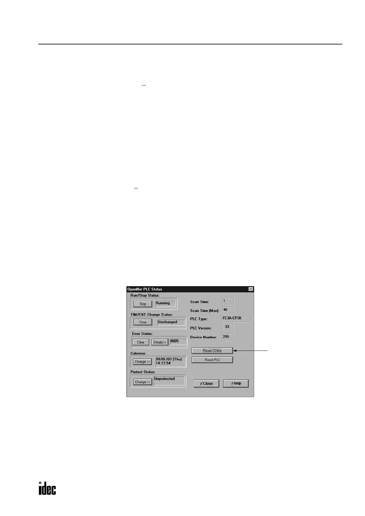
communication initialize flag) at the master station (see page 21-6), or in WindLDR select Online > Monitor, followed by
Online > PLC Status and click the Reset COMx button.
When the CPU is powered up, the CPU checks the settings of the communication selector DIP switch and enables the
selected communication mode and device number automatically. After changing the settings of the communication selec-
tor DIP switch while the CPU is powered up, press the communication enable button for more than 4 seconds until the
ERROR LED blinks once; then the new communication mode takes effect. You have to press the communication enable
button only when you change the communication mode while the CPU is powered up.
Do not power up the CPU while the communication enable button is depressed and do not press the button unless it is nec-
essary.
Reset COMx
Initializes data link
communication
Phone: 800.894.0412 - Fax: 888.723.4773 - Web: www.clrwtr.com - Email: info@clrwtr.com

 Loading...

