5: SPECIAL FUNCTIONS
5-16 OPENNET CONTROLLER USER’S MANUAL
Key Matrix Input
The key matrix input function can be programmed using the Function Area Settings in WindLDR to form a matrix with 1 to
16 input points and 1 to 16 output points to multiply input capability. A key matrix with 8 inputs and 4 outputs would equal
32 inputs, for example. The maximum, 16 inputs and 16 outputs, would result in 256 input points.
The input information is stored in consecutive internal relays as many as the quantity of input points multiplied by the
quantity of output points, starting at the first internal relay number programmed in the Function Area Settings.
When using the key matrix input function, DC input modules and transistor output modules must be used.
Since these settings relate to the user program, the user program must be downloaded to the OpenNet Controller after
changing any of these settings.
Programming WindLDR
1. From the
WindLDR menu bar, select Configure > Function Area Settings. The Function Area Setting dialog box
appears.
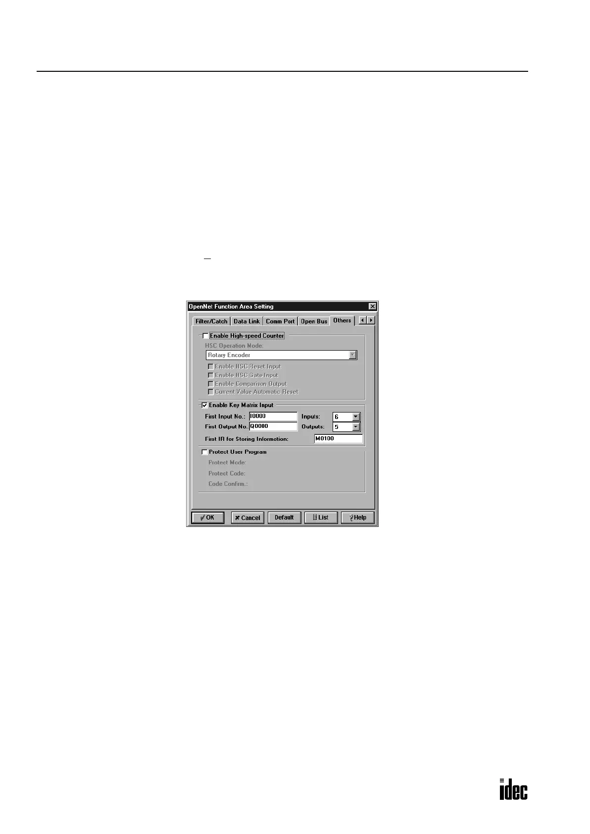
2. Select the Others tab.
3. Click the Enable Key Matrix Input check box and enter required data in the areas shown below.
First Input No.: Enter the first input number used for the key matrix.
Inputs: Enter the quantity of input points used for the key matrix.
First Output No.: Enter the first output number used for the key matrix.
Outputs: Enter the quantity of output points used for the key matrix.
First IR for Storing Information: Enter the first internal relay number used for storing key matrix input information.
Key Matrix Dialog Box
The screen display shown above is an example to configure a key matrix of 6 input points and 5 output points, starting with
input I0 and output Q0. The key matrix information is stored to 30 internal relays starting with M100.
Phone: 800.894.0412 - Fax: 888.723.4773 - Web: www.clrwtr.com - Email: info@clrwtr.com

 Loading...

