16: INTERFACE INSTRUCTIONS
OPENNET CONTROLLER USER’S MANUAL 16-3
DGRD (Digital Read)
Valid Operands
For the valid operand number range, see page 6-2.
The DGRD instruction can read 65535 (5 digits) at the maximum. When the read value exceeds 65535 with the quantity of
digits set to 5, a user program execution error will result, turning on special internal relay M8004 and the ERROR LED.
Note: The DGRD instruction can be used up to 16 times in a user program. When transferring a user program containing
more than 16 DGRD instructions to the CPU, a user program syntax error occurs, turning on the ERROR LED. The user pro-
gram cannot be executed.
Conversion
BCD: To connect BCD (decimal) digital switches
BIN: To connect BIN (hexadecimal) digital switches
Input Points
Inputs are used to read the data from digital switches. The quantity of required input points is always 4. Four input points
must be reserved starting with the input number designated by operand I. For example, when input I0 is designated as
operand I, inputs I0 through I3 are used.
Output Points
Outputs are used to select the digits to read. The quantity of required output points is equal to the quantity of digits to read.
When connecting the maximum of 5 digital switches, 5 output points must be reserved starting with the output number
designated by operand Q. For example, when output Q0 is designated as operand Q to read 3 digits, outputs Q0 through
Q2 are used.
Digital Switch Data Reading Time
Reading digital switch data requires the following time after the input to the DGRD instruction is turned on. Keep the
input to the DGRD instruction for the period of time shown below to read the digital switch data. For example, when read-
ing data from 5 digital switches to the destination operand, 14 scans are required
Adjusting Scan Time
The DGRD instruction requires a scan time longer than the filter time plus 4 msec.
When the actual scan time is too short to execute the DGRD instruction, use the constant scan function. The default value
of the input filter is 4 msec. When the input filter time is set to default, set a value of 8 or more (in msec) to special data
register D8022 (constant scan time preset value). See page 5-20. When the input filter time is changed, set a proper value
to D8022 to make sure of the minimum required scan time shown above.
Operand Function I Q M R T C D L Constant Repeat
I First input number to read X ——————— — —
Q First output number for digit selection — X —————— — —
D1 (Destination 1) Destination to store results —————— XX ——
Digital Switch Data Reading Time
2 scan times × (Quantity of digits + 2)
Minimum Required Scan Time
(Scan time) ≥ (Filter time) + 4 msec
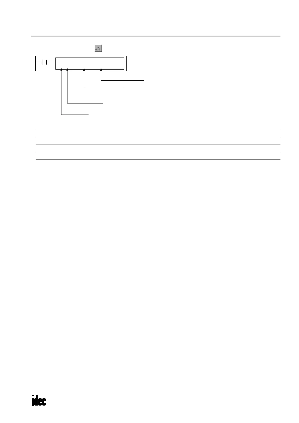
First input number
First output number
Conversion:
BCD or BIN
Quantity of digits:
1 to 5 (decimal)
1 to 4 (hex)
When input is on, data designated by operands I and Q is set
to a data register or link register designated by destination
operand D1.
This instruction can be used to change preset values for timer
and counter instructions using digital switches. The data that
can be read using this instruction is 0 through 65535 (5 dig-
its), or FFFFh.
Note: The DGRD instruction can be used on DC input and tran-
sistor output modules only.
DGRD I
*****
Q
*****
BCD4
D1
*****
Phone: 800.894.0412 - Fax: 888.723.4773 - Web: www.clrwtr.com - Email: info@clrwtr.com

 Loading...

