OPENNET CONTROLLER USER’S MANUAL 23-1
23: MODEM MODE
Introduction
This chapter describes the modem mode designed for communication between the OpenNet Controller and another Open-
Net Controller
or any data terminal equipment through telephone lines. Using the modem mode, the OpenNet Controller
can initialize a modem, dial a telephone number, send an AT command, enable the answer mode to wait for an incoming
call, and disconnect the telephone line. All of these operations can be performed simply by turning on a start internal relay
dedicated to each operation.
System Setup
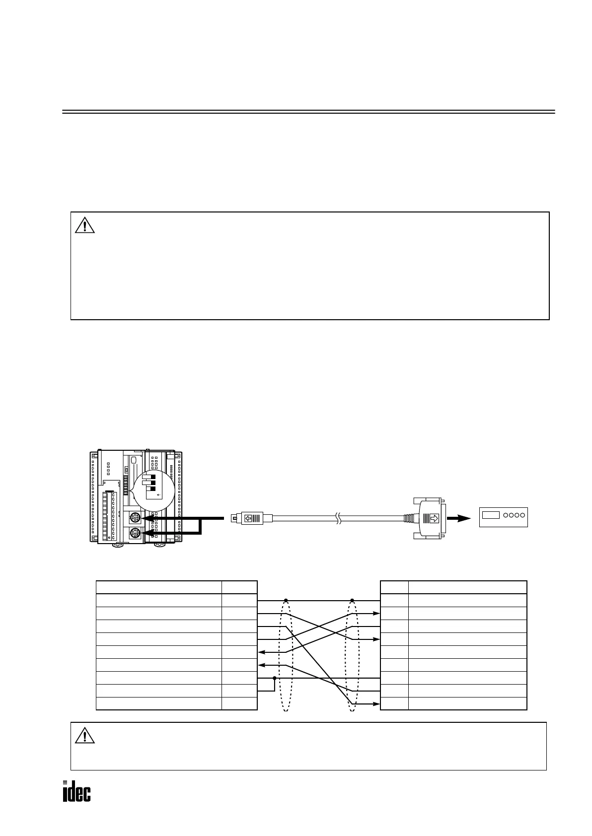
To connect a modem to the RS232C port 1 or 2 on the OpenNet Controller, use the modem cable 1C (FC2A-KM1C). To
enable the modem mode, make the two settings described below:
1. Set communication selector DIP switch 2 or 3 to ON to select user communication mode for RS232C port 1 or 2,
respectively. (See page 2-2.) Both RS232C port 1 and 2 can be used for modem communication at the same time.
2. Enter 1 to data register D8200 or D8300 (RS232C port communication mode selection) to enable the modem mode for
RS232C port 1 or 2, respectively. (See page 23-3.)
Caution
• The modem mode provides for a simple modem control function so that the OpenNet Controller
can initialize a modem, dial a destination telephone number, or answer an incoming call. The per-
formance of the modem communication using the modem mode depends on the modem functions
and telephone line situations. The modem mode does not prevent intrusion or malfunctions of
other systems. For practical applications, confirm the communication function using the actual
system setup and include safety provisions.
• While communicating through modems, the telephone line may be disconnected unexpectedly or
receive data errors may occur. Provisions against such errors must be included in the user program.
To RS232C Port 2
Modem Cable 1C
FC2A-KM1C
3m (9.84 ft.) long
To RS232C Port
D-sub 25-pin
Male Connector
D-sub 25-pin Connector Pinouts
Pin Description
1 FG Frame Ground
2 TXD Transmit Data
3 RXD Receive Data
4 RTS Request to Send
5 ——
6 ——
7 SG Signal Ground
8 DCD Data Carrier Detect
20 DTR Data Terminal Ready
Modem
Mini DIN Connector Pinouts
Description Pin
Shield Cover
RTS Request to Send 1
DTR Data Terminal Ready 2
TXD Transmit Data 3
RXD Receive Data 4
DSR Data Set Ready 5
SG Signal Ground 6
SG Signal Ground 7
NC No Connection 8
Communication Selector DIP Switch
Set DIP switch 2 or 3 to ON to select user communi-
cation mode for RS232C port 1 or 2, respectively.
ABG
RS485
COM A B Z
HSC
OUT
+24V 0V
POWER
RUN
ERROR
HSC OUT
123
O
N
DIP
Switch
To RS232C Port 1
Caution
• Do not connect the NC (no connection) pin to any line; otherwise, the OpenNet Controller and
modem may be damaged.
• Modem cables for Apple Macintosh computers cannot be used for the OpenNet Controller.
Phone: 800.894.0412 - Fax: 888.723.4773 - Web: www.clrwtr.com - Email: info@clrwtr.com

 Loading...

