21: DATA LINK COMMUNICATION
21-2 OPENNET CONTROLLER USER’S MANUAL
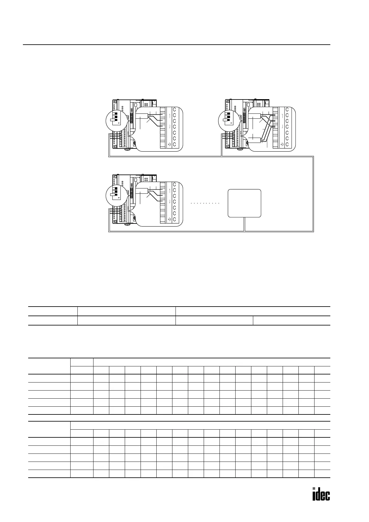
Data Link System Setup
To set up a data link system, connect the RS485 terminals A, B, and G on every OpenNet Controller CPU module using a
shielded twisted pair cable as shown below. The total length of the cable for the data link system can be extended up to 200
meters (656 feet).
Setting Communication Selector DIP Switch
The communication selector DIP switch is used to select the communication protocol for the RS485 and RS232C ports,
and also to select the device number for the CPU module used in a data link or computer link communication system.
When using the
OpenNet Controllers in a data link system, set communication selector DIP switches 1 and 4 through 8.
Selecting Data Link Communication Mode
To select the data link communication mode, set communication selector DIP switch 1 to ON at master and slave stations.
Selecting Master and Slave Station Numbers
Set communication selector DIP switches 4 through 8 to assign master station 0 and slave station numbers 1 through 31.
The slave station numbers do not have to be consecutive.
DIP Switch No. Function Setting
1 RS485 port communication mode ON: Data link mode OFF: Maintenance mode
DIP Switch No.
Master Slave Station Number
0 123456789101112131415
4 OFF ON OFF ON OFF ON OFF ON OFF ON OFF ON OFF ON OFF ON
5 OFF OFF ON ON OFF OFF ON ON OFF OFF ON ON OFF OFF ON ON
6 OFF OFF OFF OFF ON ON ON ON OFF OFF OFF OFF ON ON ON ON
7 OFF OFF OFF OFF OFF OFF OFF OFF ON ON ON ON ON ON ON ON
8 OFF OFF OFF OFF OFF OFF OFF OFF OFF OFF OFF OFF OFF OFF OFF OFF
DIP Switch No.
Slave Station Number
16 17 18 19 20 21 22 23 24 25 26 27 28 29 30 31
4 OFF ON OFF ON OFF ON OFF ON OFF ON OFF ON OFF ON OFF ON
5 OFF OFF ON ON OFF OFF ON ON OFF OFF ON ON OFF OFF ON ON
6 OFF OFF OFF OFF ON ON ON ON OFF OFF OFF OFF ON ON ON ON
7 OFF OFF OFF OFF OFF OFF OFF OFF ON ON ON ON ON ON ON ON
8 ON ONONONONONONONONONONONONONONON
0
1
2
3
4
5
6
7
8
9
10
11
12
13
14
15
16
17
0V
+24V
G
RS485
B
A
HSC
OUT
Cable
Shield
AB
Master Station Slave Station 1
0
1
2
3
4
5
6
7
8
9
10
11
12
13
14
15
16
17
0
1
2
3
4
5
6
7
8
9
10
11
12
13
14
15
16
17
0V
+24V
G
RS485
B
A
HSC
OUT
Cable
Shield
AB
0V
+24V
G
RS485
B
A
HSC
OUT
Cable
Shield
Shield
A
AB
B
Slave Station 31
123
O
N
DIP
Switch
123
O
N
DIP
Switch
123
O
N
DIP
Switch
Set communication selector
DIP switch 1 to ON at all
master and slave stations
to select the data link mode
for the RS485 port.
Shielded twisted pair cable 200 meters (656 feet) maximum
Core wire diameter 0.9 mm (0.035") minimum
Slave Station 2
HG2A Series
Operator
Interface
Phone: 800.894.0412 - Fax: 888.723.4773 - Web: www.clrwtr.com - Email: info@clrwtr.com

 Loading...

