9: MOVE INSTRUCTIONS
OPENNET CONTROLLER USER’S MANUAL 9-5
MOVN (Move Not)
Valid Operands
For the valid operand number range, see page 6-2.
▲ Internal relays M0 through M2557 can be designated as D1. Special internal relays cannot be designated as D1.
When T (timer) or C (counter) is used as S1, the timer/counter current value is read out. When T (timer) or C (counter) is
used as D1, the data is written in as a preset value which can be 0 through 65535.
Valid Data Types
When a bit operand such as I (input), Q (output), M (internal relay), or R (shift register) is designated as the source or des-
tination, 16 points (word or integer data type) or 32 points (double-word or long data type) are used. When repeat is desig-
nated for a bit operand, the quantity of operand bits increases in 16- or 32-point increments.
When a word operand such as T (timer), C (counter), D (data register), or L (link register) is designated as the source or
destination, 1 point (word or integer data type) or 2 points (double-word or long data type) are used. When repeat is desig-
nated for a word operand, the quantity of operand words increases in 1- or 2-point increments.
Examples: MOVN
Operand Function I Q M R T C D L Constant Repeat
S1 (Source 1) First operand number to move XXXXXXXX X 1-99
D1 (Destination 1) First operand number to move to — X ▲ XXXXX — 1-99
W (word) I (integer) D (double word) L (long)
XX X X
S1 NOT → D1
When input is on, 16- or 32-bit data from operand designated by S1 is
inverted bit by bit and moved to operand designated by D1.
REP
**
S1(R)
*****
D1(R)
*****
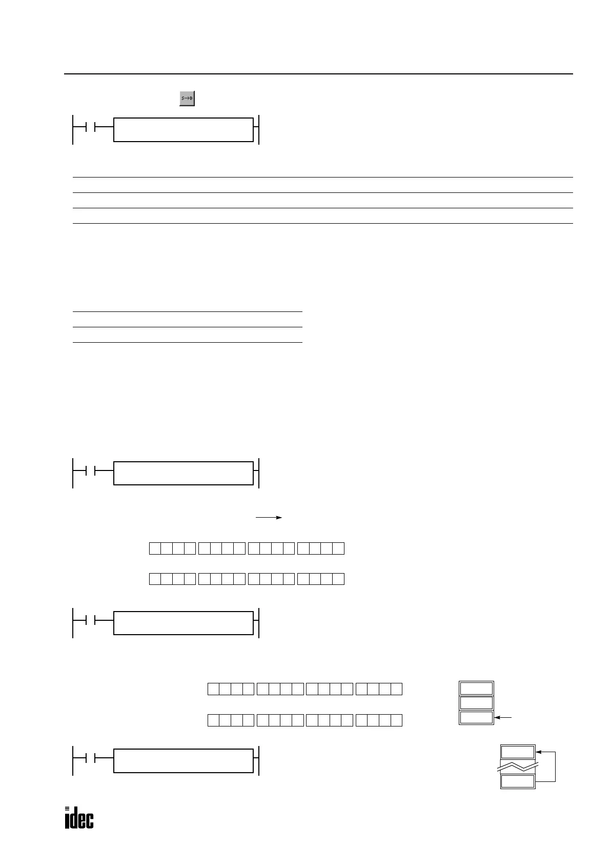
MOVN(*)
M10 NOT → M50
When input I0 is on, the 16 internal relays starting with M10 designated
by source operand S1 are inverted bit by bit and moved to 16 internal
relays starting with M50 designated by destination operand D1.
M10 through M17, M20 through M27 NOT
M50 through M57, M60 through M67
The ON/OFF statuses of the 16 internal relays M10
through M17 and M20 through M27 are inverted and
moved to 16 internal relays M50 through M57 and
M60 through M67. M50 is the LSB (least significant
bit), and M67 is the MSB (most significant bit).
Before inversion
0 1 0010 0 0 0 1 0010 1 1
MSB LSB
S1
After inversion
1 0 1101 1 1 1 0 1101 0 0
MSB LSB
D1
I0
REPS1 –
M10
D1 –
M50
MOVN(W)
(M27-M10):
(M67-M50):
810 NOT → D2
When input I1 is on, decimal constant 810 designated by source operand
S1 is converted into 16-bit binary data, and the ON/OFF statuses of the
16 bits are inverted and moved to data register D2 designated by destina-
tion operand D1.
D1
D0
64725
D2
810
Before inversion (810):
0 0 1000 0 1 0 1 1000 1 0
MSB LSB
S1
After inversion (64725):
1 1 0111 1 0 1 0 0111 0 1
MSB LSB
D1
I1
REPS1 –
810
D1 –
D2
MOVN(W)
D30 NOT → D20
When input I2 is on, the data in data register
D30 designated by S1 is inverted bit by bit and
moved to data register D20 designated by D1.
64605
D20
930
D30
I2
REPS1 –
D30
D1 –
D20
MOVN(W)
Phone: 800.894.0412 - Fax: 888.723.4773 - Web: www.clrwtr.com - Email: info@clrwtr.com

 Loading...

