24: R
EMOTE
I/O S
YSTEM
O
PEN
N
ET
C
ONTROLLER
U
SER
’
S
M
ANUAL
24-15
Precautions for Wiring INTERBUS Cable
For wiring the remote I/O master and slave modules, use the INTERBUS cable made of the remote bus cable with D-sub
9-position male and female connectors. The remote bus cable is available from Phoenix Contact. When ordering the
remote bus cable from Phoenix Contact, specify the Order No. and cable length in meters.
Remote Bus Cable Type No.
Cable Connector Pinouts
Stripping and Clamping Cable Ends
•
Do not install the INTERBUS cable in parallel with or close to motor lines. Keep the INTERBUS cable away from noise
sources.
•
Turn power off before wiring the INTERBUS cable. Make sure of correct wiring before turning power on.
•
Use a special INTERBUS cable and connect the cable as shown above. Use D-sub connectors with metal or metal-coated
housing. Connect the cable shield with the connector housing electrically.
•
Leave open the remote out connector at the last station in the network.
•
Supply power to each slave station or to each group of stations separately.
•
Master and slave stations may be powered up in any order. But, if a slave station is not powered up while the master is in
preparation for transmission, a network error will result.
•
Causes of network errors include disconnection or short-circuit of the network cable, strong external noise, invalid com-
mand sent to the master station, momentary power voltage drop below the minimum power voltage, faulty transmission
line, incorrect cable, and transmission longer than the rated distance.
•
When a network error occurs, all outputs are turned off.
Phoenix Type Order No. Specification Used for
IBS RBC METER-T 28 06 28 6 Standard, 3 x 2 x 0.22 mm
2
Fixed routing
IBS RBC METER/F-T 27 23 12 3 Highly flexible, 3 x 2 x 0.25 mm
2
Flexible power conduits and machinery compo-
nents which are frequently in motion
IBS RBC METER/E-T 27 23 14 9 Underground, 3 x 2 x 0.22 mm
2
Fixed routing indoors, outdoors or underground
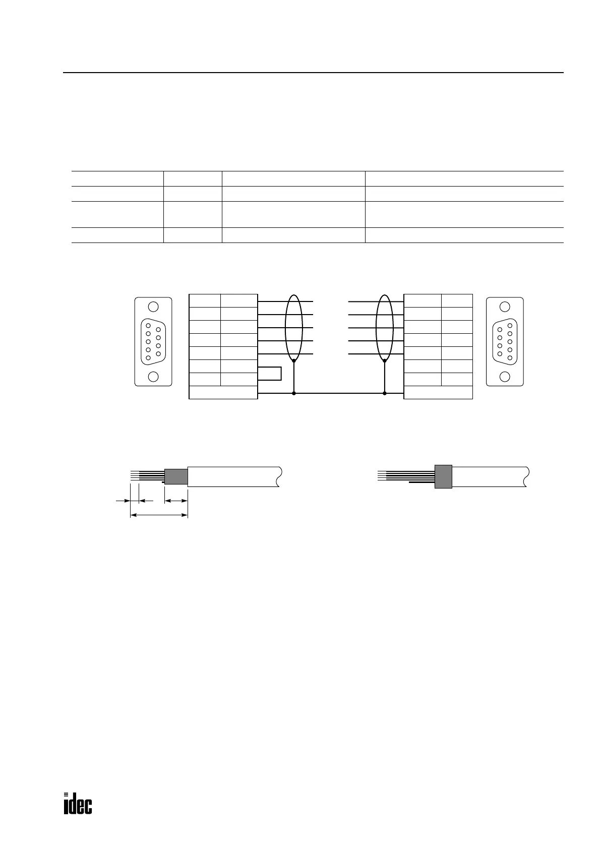
1
6
9
5
/DO 6
DO 1
/DI 7
DI 2
COM 3
5
9
Strain Relief
Green
Yellow
Pink
Gray
Brown
6 /DO
1 DO
7 /DI
2 DI
3 COM
Strain Relief
Soldered
Bridge pins 5 and 9 inside the
housing of the male connector.
1
6
9
5
D-sub 9-pin Male Connector D-sub 9-pin Female Connector
Use inch-sized screws (UNC4-40) to fasten
the cable connectors to INTERBUS ports.
Side
Soldered
Side
38
20
First, strip the cable sheath 20 mm from both ends of
the cable and shorten the braided shield by 12 mm.
Bare the wire ends 3 mm. Trim the unused white wire.
Next, place the braided shield back over the cable
sheath.
Clamp the shield under the strain relief in the connector
housing for conductive connection with the housing.
Phone: 800.894.0412 - Fax: 888.723.4773 - Web: www.clrwtr.com - Email: info@clrwtr.com

 Loading...

