25: DEVICENET SLAVE MODULE
OPENNET CONTROLLER USER’S MANUAL 25-7
Link Registers for DeviceNet Network Communication
DeviceNet network communication data is stored to link registers in the OpenNet Controller CPU module and the data is
communicated through the DeviceNet slave module.
Since seven functional modules including the DeviceNet slave module can be mounted with one
OpenNet Controller CPU
module, link registers are allocated depending on the position where the DeviceNet slave module is mounted.
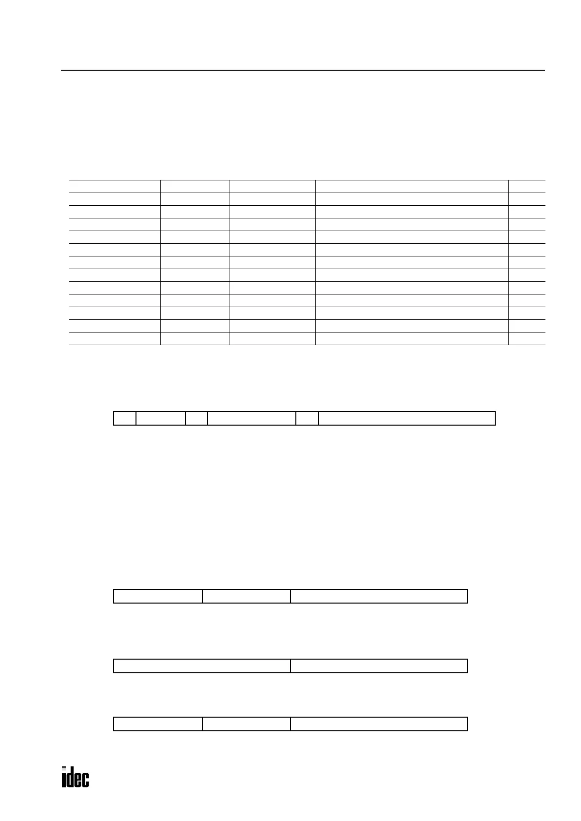
Link Register Allocation Numbers
Note: A number 1 through 7 comes in place of * depending on the position where the functional module is mounted, such
as OpenNet interface module or analog I/O module. Consequently, operand numbers are automatically allocated to each
functional module in the order of increasing distance from the CPU module, starting with L100, L200, L300, through L700.
Error Data (Status Area) L*12
When an error occurs, the MNS or IO LED on the DeviceNet slave module goes on or flashes depending on the error, and
a corresponding bit in the link register goes on. The status LED goes off when the cause of the error is removed. The error
data bit remains on until the CPU is powered up again or reset.
b15 (initialization error)
This bit goes on when the CPU module fails to acknowledge the completion of initialization for communication with the
DeviceNet slave module.
b13 (I/O error)
This bit goes on when an error occurs during communication through the CPU bus.
b8 (communication fault)
This bit goes on when a communication fault is detected.
I/O Counts (Status Area) L*13
This link register stores the transmit and receive byte counts selected in the Function Area Setting > Open Bus in
WindLDR.
Connection Status (Status Area) L*14
This link register stores the data of the allocation choice byte.
Software Version (Reserved Area) L*24
This link register stores the system software version number. [Example] Version 1.3 — 1: major revision, 3: minor revision
Allocation Number Area Function Description R/W
L*00 Data area Receive data Stores received data from the network Read
L*01 Data area Receive data Stores received data from the network Read
L*02 Data area Receive data Stores received data from the network Read
L*03 Data area Receive data Stores received data from the network Read
L*04 Data area Transmit data Stores transmit data for the network Write
L*05 Data area Transmit data Stores transmit data for the network Write
L*06 Data area Transmit data Stores transmit data for the network Write
L*07 Data area Transmit data Stores transmit data for the network Write
L*12 Status area Error data Stores various error codes Read
L*13 Status area I/O counts Stores the byte counts of transmit/receive data Read
L*14 Status area Connection status Stores the allocation choice byte Read
L*24 Reserved area Software version Stores the system software version Read
b15 b14: unused b13 b12-b9: unused b8 b7-b0: unused
L*12
b15-b12: transmit bytes b7-b0: unused
L*13
b11-b8: receive bytes
b15-b8: allocation choice b7-b0: unused
L*14
b15-b12: major revision b7-b0: unused
L*24
b11-b8: minor revision
Phone: 800.894.0412 - Fax: 888.723.4773 - Web: www.clrwtr.com - Email: info@clrwtr.com

 Loading...

