5: SPECIAL FUNCTIONS
5-6 OPENNET CONTROLLER USER’S MANUAL
Input Filter
The input filter function is used to reject input noises. The catch input function described in the next section is used to
receive short input pulses. On the contrary, the input filter function ignores short input pulses when the OpenNet Controller
is used with input signals containing noises.
Normal inputs require a pulse width of the filter value plus one scan time to receive input signals. Input filter values have
effect on the performance of the catch inputs, key matrix inputs, and digital read instruction.
Since these settings relate to the user program, the user program must be downloaded to the OpenNet Controller after
changing any of these settings.
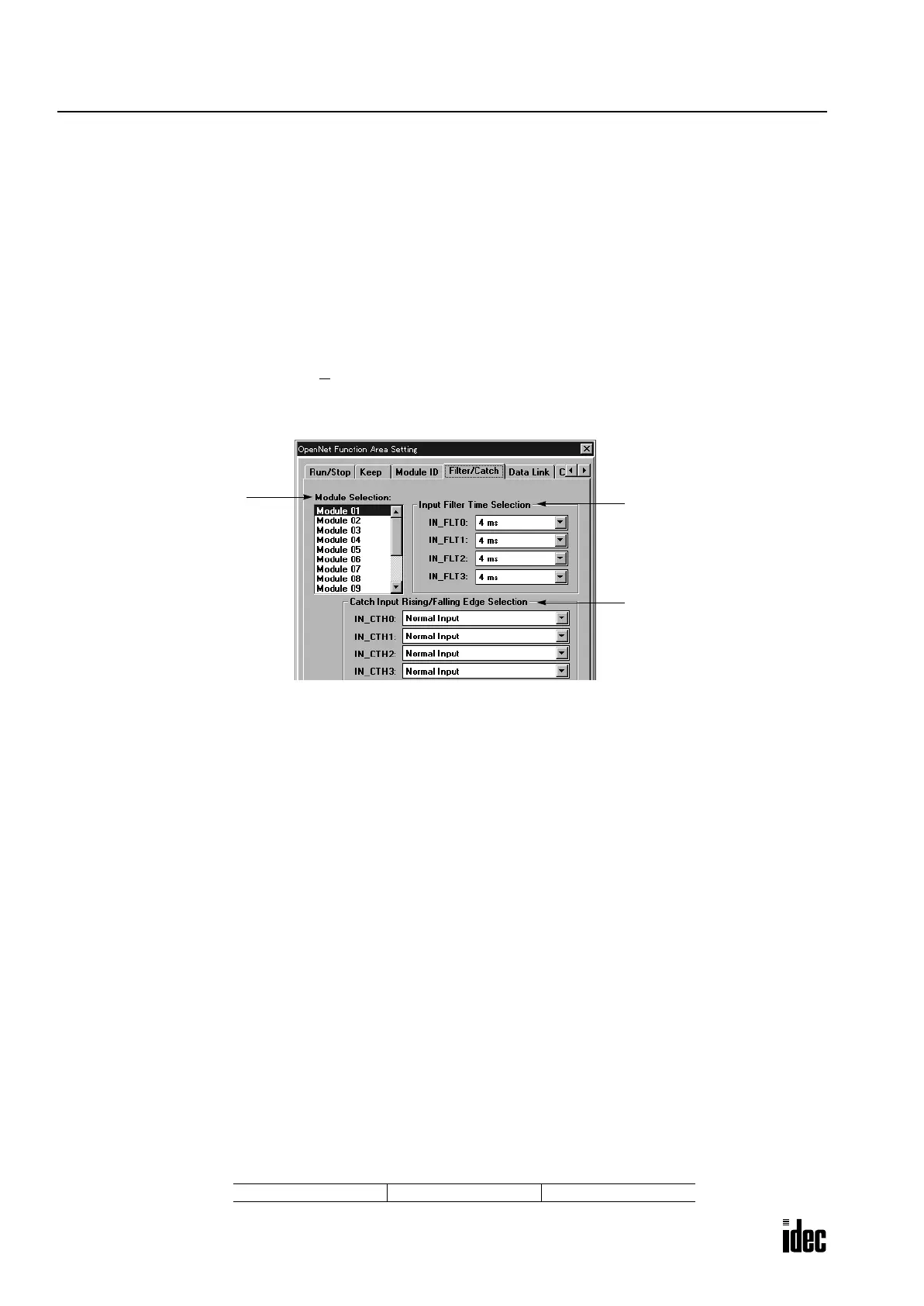
Programming WindLDR
1. From the WindLDR menu bar, select Configure > Function Area Settings. The Function Area Setting dialog box
appears.
2. Select the Filter/Catch tab.
Module Number Selection Select the module number from 1 through 15 to designate input filter (or catch input)
function. Module number 1 is the input module mounted next to the CPU module.
Module number 2 is the second from the CPU module, and so on.
Input Filter Time Selection Input filter time is selected in groups of eight inputs. For example, input numbers of
module number 1 containing 32 inputs are divided into four groups:
IN_FLT0: I0 through I7 (only IN_FLT0 has effect on catch inputs)
IN_FLT1: I10 through I17
IN_FLT2: I20 through I27
IN_FLT3: I30 through I37
Select an input filter value from 0, 0.5, 1, 2, 4, 8, 16, or 32 msec for each input group.
Default: 4 msec
Catch Input Rising/Falling Edge Selection — No effect on the input filter
Input Filter Values and Input Operation
Depending on the selected values, the input filter has three response areas to receive or reject input signals.
Input reject area: Input signals are ignored and not received (one-third of the selected filter value or less).
Input indefinite area: Input signals may be received or ignored.
Input accept area: Input signals are received (the selected filter value or higher).
Example: Rejecting Input Pulses of 2.6 msec at Inputs 0 through 7
To accept input pulses of 8 msec plus 1 scan time using normal inputs, select 8 msec in the Input Filter Time Selection
area for IN_FLT0. Then, since 8/3 approximately equals 2.6 msec, input pulses shorter than 2.6 msec are rejected.
Module Number Selection
Module 1 to 15
Input Filter Time Selection
Groups of 8 inputs
0, 0.5, 1, 2, 4, 8, 16, 32 msec
Default: 4 msec
Catch Input Rising/Falling
Edge Selection
No effect on the input filter
Indefinite
2.6 msec 8 msec + 1 scan
Reject AcceptInputs I0 to I7
Phone: 800.894.0412 - Fax: 888.723.4773 - Web: www.clrwtr.com - Email: info@clrwtr.com

 Loading...

