24: REMOTE I/O SYSTEM
24-4 OPENNET CONTROLLER USER’S MANUAL
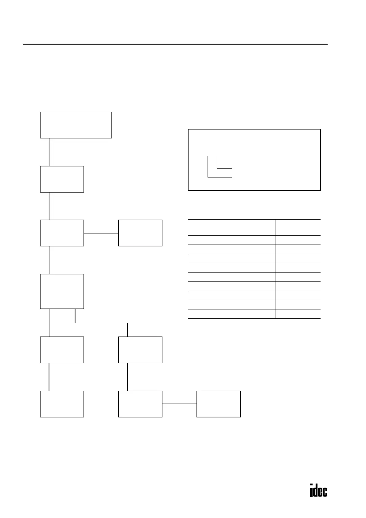
Logical Device Number and Node Number
Node addresses (logical device numbers) are assigned to each slave station by the remote I/O master module automatically
according to the physical configuration of the remote I/O network. The following diagram illustrates an example of the
OpenNet Controller remote I/O network.
OpenNet Controller
Master Station
1.0 (Node 0)
2.0 (Node 1)
Other Vendor’s
Remote Bus
3.0 (Node 3)
2.1 (Node 2)
Other Vendor’s
Local Bus
Other Vendor’s
Branch Unit
6.0 (Node 7)
7.0 (Node 8)
4.0 (Node 4)
5.0 (Node 5)
Other Vendor’s
Remote Bus
5.1 (Node 6)
Other Vendor’s
Local Bus
SX5S-SBM16K
(8 in/8 out)
SX5S-SBR08
(8 outputs)
SX5S-SBT16K
(16 outputs)
SX5S-SBN16S
(16 inputs)
Logical Device Number
1
.
0
Position (low byte)
Bus Segment No. (high byte)
Logical Device Number
(INTERBUS Address Number)
Node Number
1.0 Node 0
2.0 Node 1
2.1 Node 2
3.0 Node 3
4.0 Node 4
5.0 Node 5
5.1 Node 6
6.0 Node 7
7.0 Node 8
Phone: 800.894.0412 - Fax: 888.723.4773 - Web: www.clrwtr.com - Email: info@clrwtr.com

 Loading...

