3: INSTALLATION AND WIRING
3-6 OPENNET CONTROLLER USER’S MANUAL
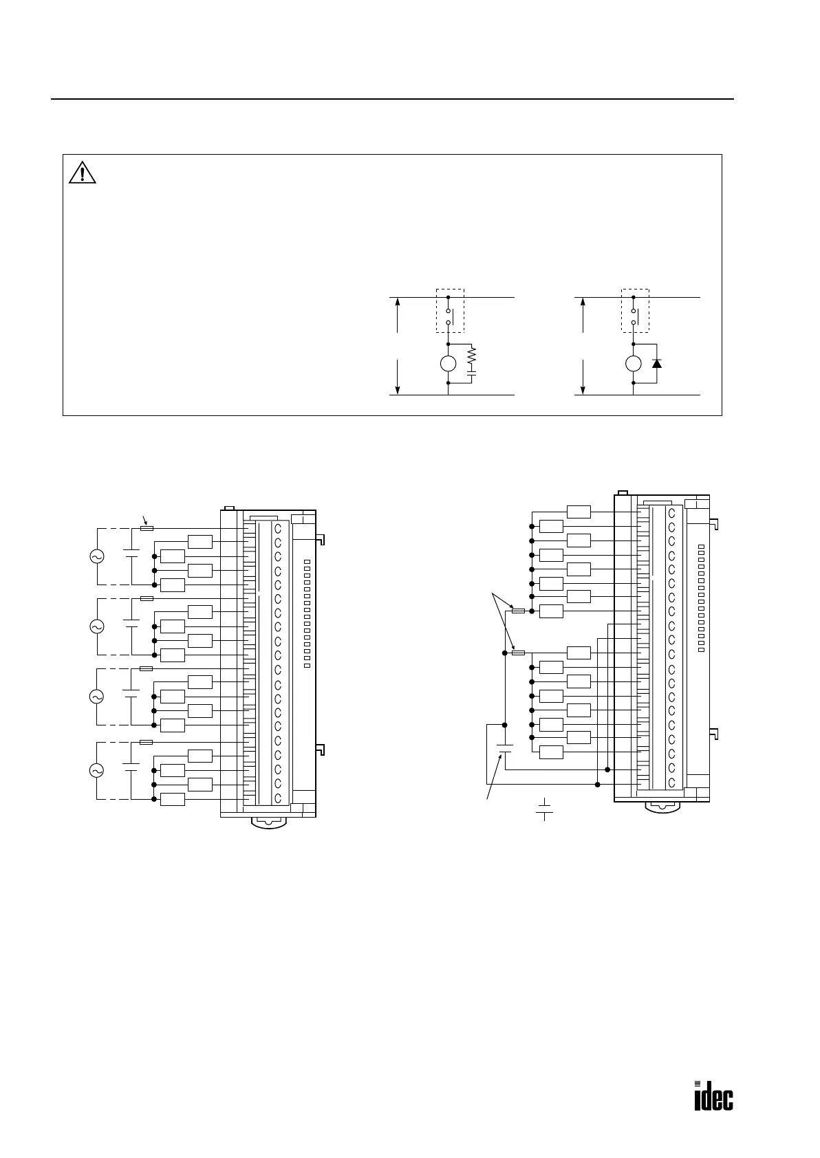
Output Wiring
Relay Output Transistor Sink Output
Caution
• Terminal name “NC” means “No Connection.” Do not connect output or any other wiring to NC terminals.
• If relays or transistors in the OpenNet Controller output modules should fail, outputs may remain on or off. For
output signals which may cause heavy accidents, provide a monitor circuit outside the OpenNet Controller.
• Connect a fuse to the output module, selecting a fuse appropriate for the load.
• Use UL1015AWG22 or UL1007AWG18 wires
for output wiring.
• When driving loads which generate noise, such
as electromagnetic contactors and solenoid
valves, use a surge absorber for AC power or a
diode for DC power.
DC
L
Power
AC
L
Output
Power
(+)
(–)
Surge
Absorber
Diode
Terminal
Output
Terminal
Load Load
0
1
2
3
4
5
6
7
10
11
12
13
14
15
16
17
Insert a fuse compatible
with the load.
Load
Load
Load
Load
Load
Load
Load
Load
Load
Load
Load
Load
Load
Load
Load
Load
1
2
3
4
5
6
7
8
9
10
11
12
13
14
15
16
17
18
19
20
+
+
+
+
Ry
OUT
0
1
2
3
4
5
6
7
10
11
12
13
14
15
16
17
Insert a fuse
compatible
with the load.
Power supply
for source output:
Load
Load
Load
Load
Load
Load
Load
Load
Load
Load
Load
Load
Load
Load
Load
Load
1
2
3
4
5
6
7
8
9
10
11
12
13
14
15
16
17
18
19
20
+
+
Tr
OUT
Phone: 800.894.0412 - Fax: 888.723.4773 - Web: www.clrwtr.com - Email: info@clrwtr.com

 Loading...

