17: USER COMMUNICATION INSTRUCTIONS
OPENNET CONTROLLER USER’S MANUAL 17-31
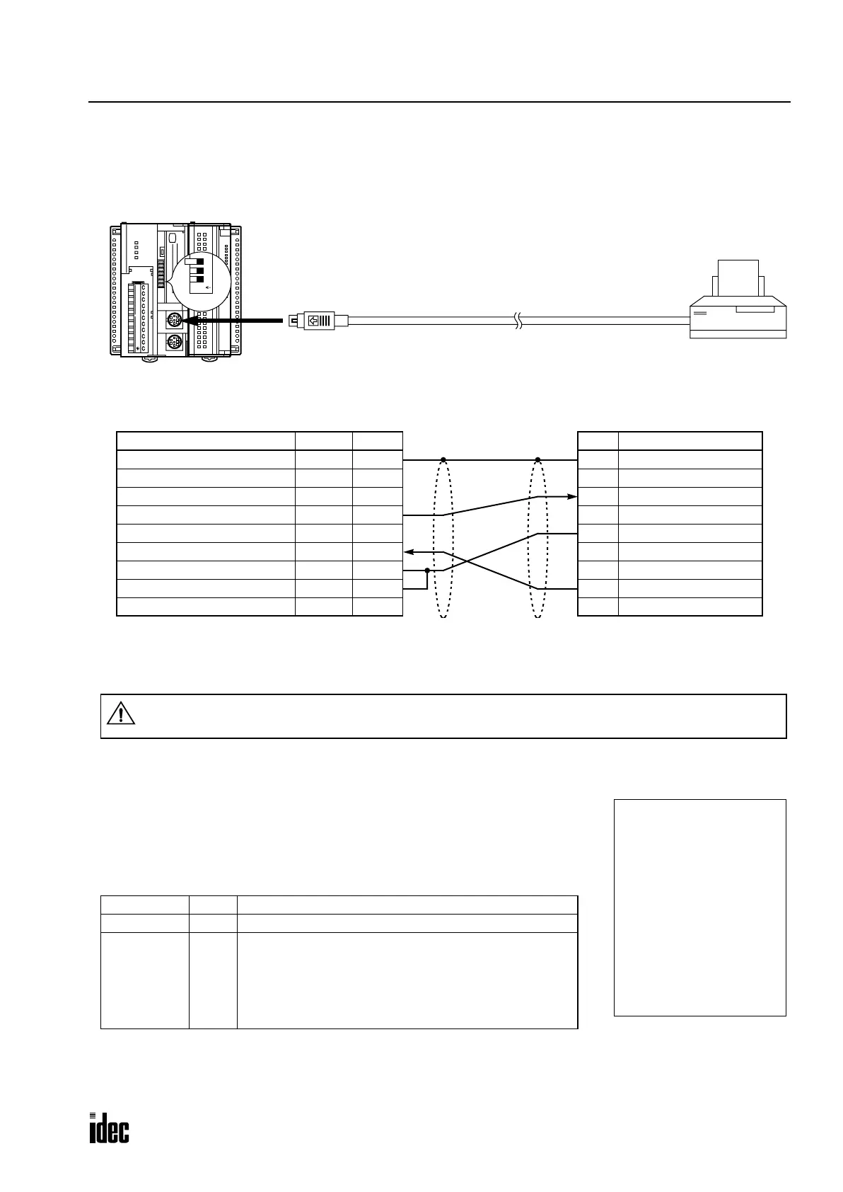
Sample Program – User Communication TXD
This example demonstrates a program to send data to a printer using the user communication TXD2 (transmit) instruction.
System Setup
The name of BUSY terminal differs depending on printers, such as DTR. The function of this terminal is to send a signal
to remote equipment whether the printer is ready to print data or not. Since the operation of this signal may differ depend-
ing on printers, confirm the operation before connecting the cable.
Description of Operation
The data of counter C2 and data register D30 are printed every minute. A printout
example is shown on the right.
Programming Special Data Register
Special data register D8305 is used to monitor the BUSY signal and to control the
transmission of print data.
The OpenNet Controller monitors the DSR signal to prevent the receive buffer of the printer from overflowing. For the
DSR signal, see page 17-28.
Special DR Value Description
D8300 0 User communication mode (not modem mode)
D8305 3
While DSR is on (not busy), the CPU sends data.
While DSR is off (busy), the CPU stops data transmission.
If the off duration exceeds a limit (approx. 5 sec), a trans-
mission busy timeout error will occur, and the remaining
data is not sent. The transmit status data register stores
an error code. See pages 17-9 and 17-25.
To RS232C Port
ABG
RS485
COM A B Z
HSC
OUT
+24V 0V
POWER
RUN
ERROR
HSC OUT
123
O
N
DIP
Switch
D-sub 9-pin Connector Pinouts
Pin Description
1 NC No Connection
2 NC No Connection
3 DATA Receive Data
4 NC No Connection
5 GND Ground
6 NC No Connection
7 NC No Connection
8 BUSY Busy Signal
9 NC No Connection
Printer
Mini DIN Connector Pinouts
Description Color Pin
Shield — Cover
NC No Connection Black 1
NC No Connection Yellow 2
TXD Transmit Data Blue 3
NC No Connection Green 4
DSR Data Set Ready Brown 5
SG Signal Ground Gray 6
SG Signal Ground Red 7
NC No Connection White 8
User Communication Cable 1C
FC2A-KP1C
2.4m (7.87 ft.) long
Attach a proper connector to the open
end of the cable referring to the cable
connector pinouts shown below.
Cable Connection and Pinouts
To RS232C Port 2
Communication Selector DIP Switch
Set DIP switch 3 to ON to select user com-
munication mode for RS232C port 2.
Caution
• Do not connect any wiring to the NC (no connection) pins; otherwise, the OpenNet Controller and
the printer may not work correctly and may be damaged.
--- PRINT TEST ---
11H 00M
CNT2...0050
D030...3854
--- PRINT TEST ---
11H 01M
CNT2...0110
D030...2124
Printout Example
Phone: 800.894.0412 - Fax: 888.723.4773 - Web: www.clrwtr.com - Email: info@clrwtr.com

 Loading...

