OPENNET CONTROLLER USER’S MANUAL 22-1
22: COMPUTER LINK COMMUNICATION
Introduction
When the OpenNet Controller is connected to a computer, operating status and I/O status can be monitored on the com-
puter, data in the CPU can be monitored or updated, and user programs can be downloaded and uploaded. The OpenNet
Controller
can also be started or stopped from the computer. A maximum of 32 OpenNet Controller CPUs can be con-
nected to one computer in the 1:N computer link system.
This chapter describes the 1:N computer link system. For the 1:1 computer link system, see page 4-1.
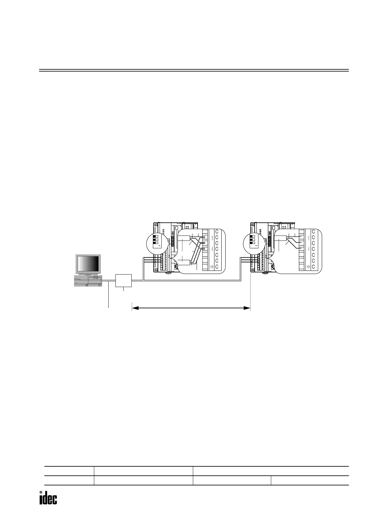
Computer Link System Setup (1:N Computer Link System)
To set up a 1:N communication computer link system, connect the RS232C/RS485 converter to the RS485 terminals A, B,
and G on every OpenNet Controller CPU module using a shielded twisted pair cable as shown below. The total length of
the cable for the computer link system can be extended up to 200 meters (656 feet).
Connect the RS232C port on the computer to the RS232C/RS485 converter using the RS232C cable HD9Z-C52. The
RS232C cable has a D-sub 9-pin female connector for connection with a computer.
Setting Communication Selector DIP Switch
The communication selector DIP switch is used to select the communication protocol for the RS485 and RS232C ports,
and also to select the device number for the
OpenNet Controller CPU module used in a data link or computer link commu-
nication system. When using the OpenNet Controllers in a 1:N computer link system, set communication selector DIP
switches 1 and 4 through 8.
When the CPU is powered up, the CPU checks the settings of the communication selector DIP switch and enables the
selected communication mode and device number automatically. After changing the settings of the communication selec-
tor DIP switch while the CPU is powered up, press the communication enable button for more than 4 seconds until the
ERROR LED blinks once; then the new communication mode takes effect. You have to press the communication enable
button only when you change the communication mode while the CPU is powered up.
Do not power up the CPU while the communication enable button is depressed and do not press the button unless it is nec-
essary.
Selecting Maintenance Mode
To select the maintenance mode, set communication selector DIP switch 1 to OFF at all OpenNet Controller CPU modules
in the 1:N computer link network.
DIP Switch No. Function Setting
1 RS485 port communication mode ON: Data link mode OFF: Maintenance mode
0
1
2
3
4
5
6
7
8
9
10
11
12
13
14
15
16
17
RS232C/RS485 Converter
FC2A-MD1
Windows PC
RS232C Cable
HD9Z-C52
1.5m (4.92 feet) long
0
1
2
3
4
5
6
7
8
9
10
11
12
13
14
15
16
17
0
1
2
3
4
5
6
7
8
9
10
11
12
13
14
15
16
17
0V
+24V
G
RS485
B
A
HSC
OUT
Cable
Shield
Shield
A
AB
B
0V
+24V
G
RS485
B
A
HSC
OUT
Cable
Shield
AB
1st Unit Nth Unit (N = 32 maximum)
123
O
N
DIP
Switch
123
O
N
DIP
Switch
Set communication selector
DIP switch 1 to OFF at all
OpenNet Controller stations
to select the maintenance
mode for the RS485 port.
Shielded twisted pair cable 200 meters (656 feet) maximum
Core wire diameter 0.9 mm (0.035") minimum
Nth Unit (N≤32)
Phone: 800.894.0412 - Fax: 888.723.4773 - Web: www.clrwtr.com - Email: info@clrwtr.com

 Loading...

