6: ALLOCATION NUMBERS
6-18 OPENNET CONTROLLER USER’S MANUAL
Digital I/O Module Operands
Input and output numbers are automatically allocated to each digital I/O module in the order of increasing distance from
the CPU module. A maximum of 7 digital I/O or functional modules can be mounted with one CPU module without using
an expansion power supply module, so that a maximum of 224 I/O points can be allocated in total. When using an expan-
sion power supply module, 15 modules can be mounted so that the I/O numbers can be expanded up to 480 points in total.
I/O Operand Numbers
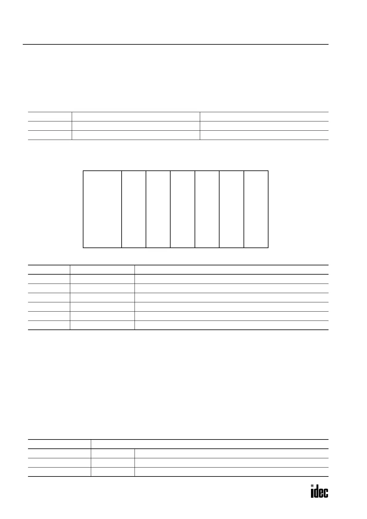
Example:
The system setup shown above will have operand numbers allocated for each module as follows:
Input and output modules may be grouped together for easy identification of I/O numbers. The I/O numbers are allocated
automatically starting with I0 and Q0 at the module nearest to the CPU module. When the I/O modules are relocated, the
I/O numbers are renumbered automatically.
The location of functional modules does not affect the I/O operand numbers.
Functional Module Operands
Functional modules are analog input, analog output, DeviceNet slave, and LONWORKS interface modules. A maximum of
7 functional modules can be mounted with one CPU module in a system setup of 15 modules at the maximum.
Operand numbers are automatically allocated to each functional module in the order of increasing distance from the CPU
module, starting with L100, L200, L300 through L700. The location of digital I/O modules between CPU and functional
modules does not affect the operand numbers for the functional modules.
Functional Module Operand Numbers
Operand Without Expansion Power Supply Module When Using Expansion Power Supply Module
Input I0 through I277 (224 points) I0 through I597 (480 points)
Output Q0 through Q277 (224 points) Q0 through Q597 (480 points)
Slot No. Module Operand Numbers
1 Input Module 1 I0 through I7, I10 through I17
2 Output Module 1 Q0 through Q7, Q10 through Q17, Q20 through Q27, Q30 through Q37
3 Functional Module L100 through L127
4 Output Module 2 Q40 through Q47, Q50 through Q57
5 Output Module 3 I20 through I27, I30 through I37
6 Input Module 2 I40 through I47, I50 through I57, I60 through I67, I70 through I77
Allocation Number Description
L*00 through L*07 Data area Data used in each functional module, such as analog data
L*10 through L*17 Status area Status of each functional module
L*20 through L*27 Reserved area Reserved for system program. Do not access this area.
OpenNet Input
16-pt
Input
Output
32-pt
Output
Func-
tional
Module
Output
16-pt
Output
Input
16-pt
Input
Input
32-pt
Input
Slot No.:
123456
Controller
CPU Module
Module Module Module Module Module
Phone: 800.894.0412 - Fax: 888.723.4773 - Web: www.clrwtr.com - Email: info@clrwtr.com

 Loading...

