24: R
EMOTE
I/O S
YSTEM
24-6 O
PEN
N
ET
C
ONTROLLER
U
SER
’
S
M
ANUAL
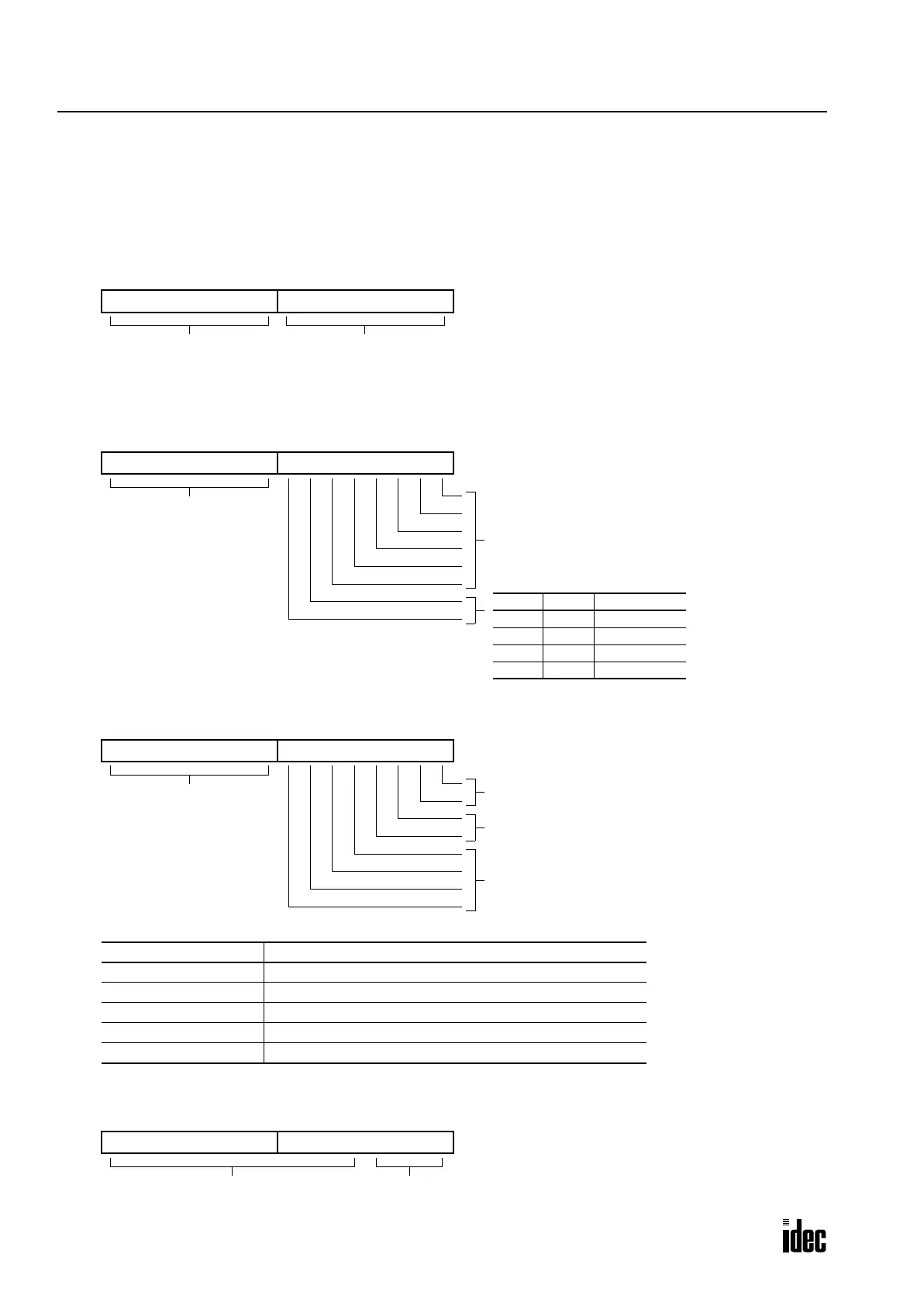
Special Data Registers for Remote I/O Node Information
Four data registers are allocated to each node to store information of the slave station. The remote I/O node information is
stored to special data registers D8050 through D8177 while the remote I/O communication is in normal operation. The
remote I/O node information is not stored when special data register D8178 (INTERBUS master system error information)
stores 6, 7, or 8 to indicate a data size error, ID code error, or maximum node quantity over, respectively. See page 24-10.
Logical Device No. (Bus Segment No. + Position)
Length Code
Note:
The data register assigned to the length code stores the quantity of the input or output points, whichever is larger, of
the slave station. When using the SX5S as a slave, the length code can be 8 bits (1 byte) or 16 bits (2 bytes).
ID Code
Device Level
76543210
Bus segment number
15 14 13 12 11 10 9 8
Position
76543210
Always 0
Bit 7 Bit 6 Unit
0 0 (reserved)
0 1 Nibbles
1 0 Bytes
1 1 Bits
Value
15 14 13 12 11 10 9 8
Always 0
Quantity of PCP Words
(peripherals communication protocol)
I/O Type
Station Type
ID Code Examples
ID Code (Low Byte) Type
01h Digital output remote bus station (example: SX5S-SBT16K)
02h Digital input remote bus station (example: SX5S-SBN16S)
03h Digital I/O remote bus station (example: SX5S-SBM16K)
31h Analog output remote bus station
32h Analog input remote bus station
7654321015 14 13 12 11 10 9 8
Always 0 INTERBUS Device Level: 0 through 15
7654321015 14 13 12 11 10 9 8
Phone: 800.894.0412 - Fax: 888.723.4773 - Web: www.clrwtr.com - Email: info@clrwtr.com

 Loading...

