6: ALLOCATION NUMBERS
OPENNET CONTROLLER USER’S MANUAL 6-19
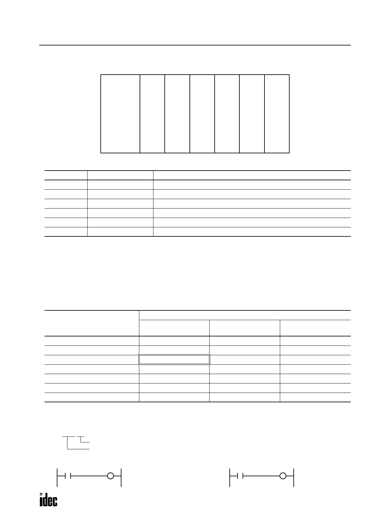
Example:
The system setup shown above will have operand numbers allocated to each module as follows:
In the system setup shown above, the analog input module in slot 5 uses link register L300 for channel 0 data and L304 for
channel 4 data.
Bit Designation of Link Register
The following table illustrates how to read and write link register bits primarily used for basic instructions and some
advanced instructions as bit operands.
Link Register Mapping for Functional Modules
Each functional module has eight channels of data areas. One channel consists of one link register which can process one-
word data, or 16 bits. Functional module data is addressed for bit operands in the following formula:
Slot No. Module Operand Numbers
1 Functional Module 1 L100 through L127
2 Output Module 1 Q0 through Q7, Q10 through Q17, Q20 through Q27, Q30 through Q37
3 Functional Module 2 L200 through L227
4 Output Module 2 Q40 through Q47, Q50 through Q57
5 Functional Module 3 L300 through L327
6 Input Module 1 I0 through I7, I10 through I17, I20 through I27, I30 through I37
Functional Module
Allocation Numbers
Data Area
Status Area
(Read Only)
Reserved Area
(Access Prohibited)
Functional Module 1 L0100-L0107 L0110-L0117 L0120-L0127
Functional Module 2 L0200-L0207 L0210-L0217 L0220-L0227
Functional Module 3 L0300-L0307 L0310-L0317 L0320-L0327
Functional Module 4 L0400-L0407 L0410-L0417 L0420-L0427
Functional Module 5 L0500-L0507 L0510-L0517 L0520-L0527
Functional Module 6 L0600-L0607 L0610-L0617 L0620-L0627
Functional Module 7 L0700-L0707 L0710-L0717 L0720-L0727
OpenNet Func-
tional
Module
Slot No.:
123456
Controller
CPU Module
Func-
tional
Module
OpenNet
Interface
Analog
Output
Input
32-pt
Input
Module
Output
32-pt
Output
Module
Output
16-pt
Output
Module
Func-
tional
Module
Analog
Input
L0100.01
Bit No.: 0 through 15
Link Register No.: 100 through 727, 1000 through 1317
Example 1: Load link register L300, bit 10
L300.10
Example 2: Set link register L304, bit 8
I5
Q12 L304.8
S
Phone: 800.894.0412 - Fax: 888.723.4773 - Web: www.clrwtr.com - Email: info@clrwtr.com

 Loading...

