3: INSTALLATION AND WIRING
3-8 OPENNET CONTROLLER USER’S MANUAL
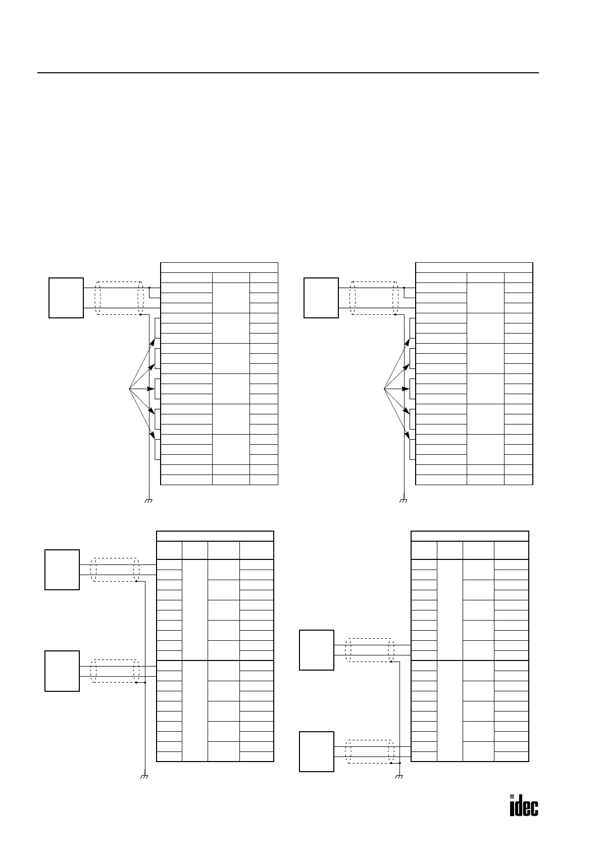
Analog Input/Output Wiring
When using an analog input or output module, connect analog signals and ground wire as shown below.
• For wiring analog input or output module, use a two-core twisted pair shielded cable with a minimum core diameter of
0.9 mm. Connect the shield to a proper frame ground (grounding resistance 100Ω maximum).
• Connect the FG terminals of the 24V DC power supply and the CPU module to the ground (grounding resistance 100Ω
maximum). The ground connection improves the stability of analog/digital conversion.
• Terminal numbers are marked on the terminal block label on the input/output module.
• For analog input and output module specifications, see pages 2-28 and 2-31.
Wiring Schematic
Analog Input Module
Terminal No. Channel Name
1
Ch 0
+V
2+I
3 COM
4
Ch 1
+V
5+I
6 COM
7
Ch 2
+V
8+I
9 COM
10
Ch 3
+V
11 +I
12 COM
13
Ch 4
+V
14 +I
15 COM
16
Ch 5
+V
17 +I
18 COM
19 — NC
20 — NC
Analog
Current
Output
Device
+
–
Connect +V and
COM terminals of
unused channels
together.
Analog Current Input (rotary switch set to 4)
0 to 20 mA
Analog Input Module
Terminal No. Channel Name
1
Ch 0
+V
2+I
3 COM
4
Ch 1
+V
5+I
6 COM
7
Ch 2
+V
8+I
9 COM
10
Ch 3
+V
11 +I
12 COM
13
Ch 4
+V
14 +I
15 COM
16
Ch 5
+V
17 +I
18 COM
19 — NC
20 — NC
Analog
Voltage
Output
Device
+
–
Connect +V and
COM terminals of
unused channels
together.
Analog Voltage Input (rotary switch set to 0 through 3)
0 to 10V,
±10V,
0 to 5V,
±5V
FG FG
Analog Output Module
Term
No.
Chan
Rotary
Sw.
Name
1
Ch 0
0
0-10V
2 COM
3
1
±10V
4 COM
5
2
0-5V
6 COM
7
3
±5V
8 COM
9
4
4-20mA
10 COM
11
Ch 1
0
0-10V
12 COM
13
1
±10V
14 COM
15
2
0-5V
16 COM
17
3
±5V
18 COM
19
4
4-20mA
20 COM
+
–
+
–
Analog Output Module
Term
No.
Chan
Rotary
Sw.
Name
1
Ch 0
0
0-10V
2 COM
3
1
±10V
4 COM
5
2
0-5V
6 COM
7
3
±5V
8 COM
9
4
4-20mA
10 COM
11
Ch 1
0
0-10V
12 COM
13
1
±10V
14 COM
15
2
0-5V
16 COM
17
3
±5V
18 COM
19
4
4-20mA
20 COM
+
–
+
–
Analog Current Output (rotary switch set to 4)Analog Voltage Output (rotary switch set to 0)
0 to 10V DC
0 to 10V DC
0 to 20 mA
0 to 20 mA
Analog
Current
Input
Device
Analog
Current
Input
Device
Analog
Voltage
Input
Device
Analog
Voltage
Input
Device
FG FG
Phone: 800.894.0412 - Fax: 888.723.4773 - Web: www.clrwtr.com - Email: info@clrwtr.com

 Loading...

