16: INTERFACE INSTRUCTIONS
16-4 OPENNET CONTROLLER USER’S MANUAL
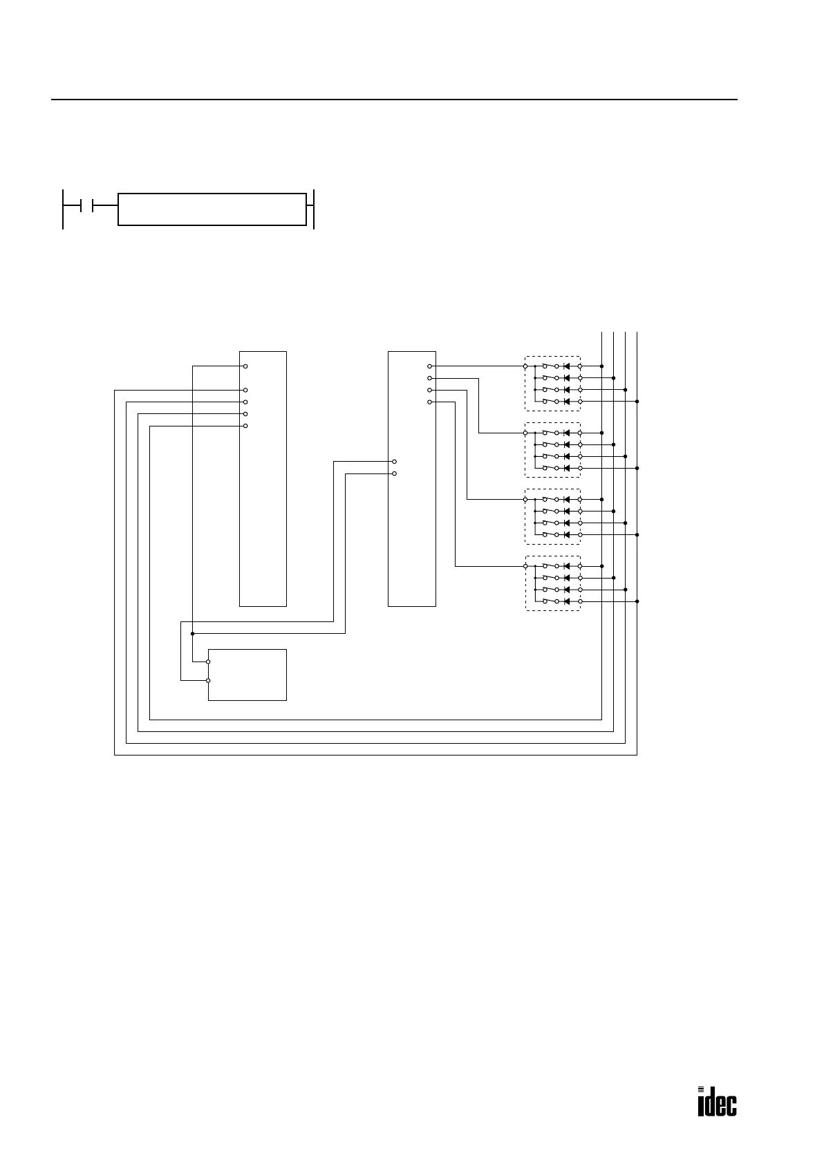
Example: DGRD
The following example demonstrates a program to read data from four digital switches (IDEC’s DF**-031D(K)) to a data
register in the OpenNet Controller CPU module.
I/O Wiring Diagram
When input I5 is on, the 4-digit value from BCD digital switches is read
to data register D10.
I5
I
I0
Q
Q0
D1
D10
DGRD
BCD4
Digital
1
2
4
8
Switches
16-DC Input Module
FC3A-N16B1
16-Transistor Sink Output Module
FC3A-T16K1
10
3
10
2
10
1
10
0
Q0
Q1
Q2
Q3
Q4
Q5
Q6
Q7
COM(–)
+V
Q10
Q11
Q12
Q13
Q14
Q15
Q16
Q17
COM(–)
+V
(+)
(–)
24V DC
Power
Supply
COM
COM
I0
I1
I2
I3
I4
I5
I6
I7
COM
COM
I10
I11
I12
I13
I14
I15
I16
I17
C
1
2
4
8
C
1
2
4
8
C
1
2
4
8
C
Phone: 800.894.0412 - Fax: 888.723.4773 - Web: www.clrwtr.com - Email: info@clrwtr.com

 Loading...

