EasyManua.ls Logo

IDEC OpenNet series User Manual

IDEC OpenNet series
427 pages
To Next Page IconTo Next Page
To Previous Page IconTo Previous Page
Page #167 background imageLoading...
Page #167 background image
11: BINARY ARITHMETIC INSTRUCTIONS
11-2 OPENNET CONTROLLER USERS MANUAL
Valid Operands
For the valid operand number range, see page 6-2.
Internal relays M0 through M2557 can be designated as D1. Special internal relays cannot be designated as D1.
When T (timer) or C (counter) is used as S1 or S2, the timer/counter current value is read out. When T (timer) or C
(counter) is used as D1, the data is written in as a preset value which can be 0 through 65535.
Since the binary arithmetic instructions are executed in each scan while input is on, a pulse input from a SOTU or SOTD
instruction should be used as required.
Valid Data Types
When a bit operand such as I (input), Q (output), M (internal relay), or R (shift register) is designated as the source or des-
tination, 16 points (word or integer data type) or 32 points (double-word or long data type) are used. When repeat is desig-
nated for a bit operand, the quantity of operand bits increases in 16- or 32-point increments.
When a word operand such as T (timer), C (counter), D (data register), or L (link register) is designated as the source or
destination, 1 point (word or integer data type) or 2 points (double-word or long data type) are used. When repeat is desig-
nated for a word operand, the quantity of operand words increases in 1- or 2-point increments.
Using Carry or Borrow Signals
When the D1 (destination) data is out of the valid data range as a result of addition, a carry occurs, and special internal
relay M8003 is turned on. When the D1 (destination) data is out of the valid data range as a result of subtraction, a borrow
occurs, and special internal relay M8003 is turned on.
There are three ways to program the carrying process (see examples below). If a carry never goes on, the program does not
have to include internal relay M8003 to process carrying. If a carry goes on unexpectedly, an output can be programmed to
be set as a warning indicator. If a carry goes on, the number of times a carry occurs can be added to be used as one word
data in a specified register.
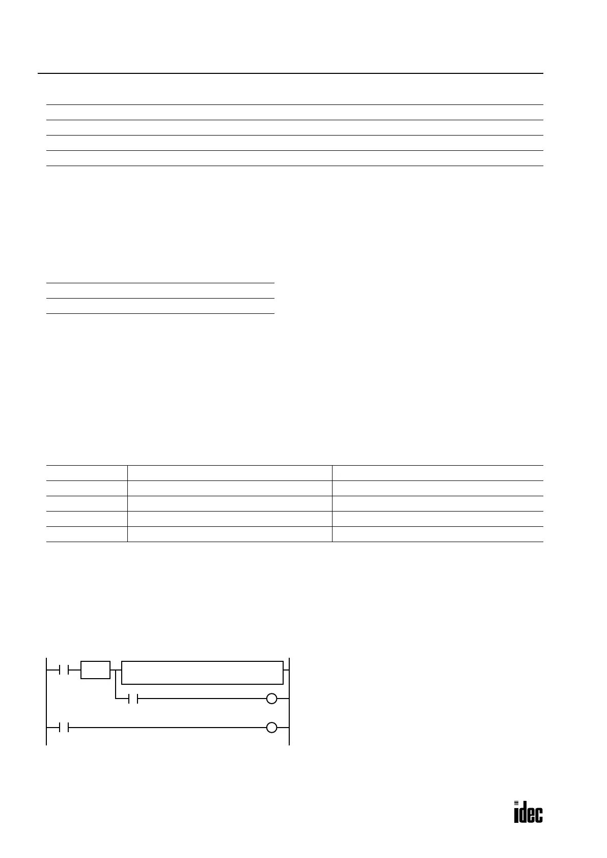
Examples: ADD
• Data Type: Word
This example demonstrates the use of a carry signal from special internal relay M8003 to set an alarm signal.
Operand Function I Q M R T C D L Constant Repeat
S1 (Source 1) Data for calculation XXXXXXXX X 1-99
S2 (Source 2) Data for calculation XXXXXXXX X 1-99
D1 (Destination 1) Destination to store results X XXXXX 1-99
W (word) I (integer) D (double word) L (long)
XX X X
Data Type Carry occurs when D1 is Borrow occurs when D1 is
W (word) over 65,535 below 0
I (integer) below 32,768 or over 32,767 below 32,768 or over 32,767
D (double word) over 4,294,967,295 below 0
L (long) below 2,147,483,648 or over 2,147,483,647 below 2,147,483,648 or over 2,147,483,647
I0
REPS2
500
D1
D2
SOTU
M8003
I1
D2 + 500 D2
When a carry occurs, output Q0 is set as a warning indicator.
When the acknowledge pushbutton (input I1) is pressed,
the warning indicator is reset.
Acknowledge
Pushbutton
S1
D2
ADD(W)
Q0
S
Q0
R
Phone: 800.894.0412 - Fax: 888.723.4773 - Web: www.clrwtr.com - Email: info@clrwtr.com

Table of Contents

Question and Answer IconNeed help?

Do you have a question about the IDEC OpenNet series and is the answer not in the manual?

IDEC OpenNet series Specifications

General IconGeneral
Communication ProtocolModbus/TCP
Data Transfer Rate100 Mbps
Power Supply Voltage24V DC (typically)
Operating Temperature0°C to 55°C
Vibration Resistance10 to 57 Hz, 0.075 mm amplitude

Summary

SAFETY PRECAUTIONS

Warning

Emphasizes severe personal injury or death from improper operation.

Caution

Highlights potential personal injury or equipment damage from inattention.

About This Manual

CHAPTER 1: GENERAL INFORMATION

Provides general info about the OpenNet Controller, features, and system setups.

CHAPTER 2: MODULE SPECIFICATIONS

Details specifications for CPU, I/O, expansion, and interface modules.

CHAPTER 3: INSTALLATION AND WIRING

Covers methods and precautions for installing and wiring modules.

CHAPTER 4: OPERATION BASICS

Explains system setup, starting/stopping, and basic operation procedures.

CHAPTER 5: SPECIAL FUNCTIONS

Describes special functions like catch input, filters, and high-speed counters.

CHAPTER 6: ALLOCATION NUMBERS

Details allocation numbers for operands, relays, timers, and registers.

CHAPTER 7: BASIC INSTRUCTIONS

Covers programming of basic instructions and available operands.

CHAPTER 8: ADVANCED INSTRUCTIONS

Explains general rules for using advanced instructions, terms, and data types.

CHAPTER 9 THROUGH CHAPTER 20

Detailed descriptions on advanced instructions grouped into 12 chapters.

CHAPTER 21 THROUGH CHAPTER 26

Covers various communication functions like data link and DeviceNet.

CHAPTER 27: TROUBLESHOOTING

Provides procedures to determine causes of trouble and actions to take.

APPENDIX

Contains additional information like execution times and type lists.

1: GENERAL INFORMATION

Introduction

Describes general information for understanding the OpenNet Controller and system setups.

About the OpenNet Controller

Overview of the OpenNet Controller's capabilities and compatibility.

Features

Highlights connectivity to open networks and powerful communication functions.

International Safety Standards and Approvals

States that the OpenNet Controller is certified by UL and CSA.

Special Functions

Details special functions like catch input, filters, high-speed counter, and key matrix.

System Setup

Describes various system setup configurations for communication functions.

User Communication System

Details communication with external devices via RS232C and RS485 ports.

Computer Link System

Covers monitoring, updating, and program transfer via computer link.

Data Link System

Explains the RS485 data link system for master/slave communication.

Basic System

Describes system setup with up to seven I/O and functional modules.

Expansion System

Details mounting more than seven modules using an expansion power supply.

2: MODULE SPECIFICATIONS

Introduction

Describes modules, parts names, and specifications of each module.

CPU Module

Details CPU module types, including sink/source output and memory card connector.

Input Module

Details available digital input modules and connector/terminal styles.

16-point DC Input Module Specifications

Provides detailed specifications for 16-point DC input modules.

32-point DC Input Module Specifications

Details specifications for 32-point DC input modules.

8-point AC Input Module Specifications

Provides specifications for the 8-point AC input module.

Input Module Terminal Arrangement

Illustrates terminal arrangements and wiring schematics for input modules.

FC3A-N16B3 (16-point DC Input Module) — Nylon Connector Type

Details terminal arrangements and wiring for nylon connector type DC input modules.

FC3A-N32B4 (32-point DC Input Module) — Nylon Connector Type

Covers terminal arrangements and wiring for nylon connector type 32-point DC input modules.

FC3A-N32B5 (32-point DC Input Module) — Fujitsu Connector Type

Details terminal arrangements and wiring for Fujitsu connector type 32-point DC input modules.

FC3A-N08A11 (8-point AC Input Module) — Screw Terminal Type

Shows terminal arrangements and wiring for screw terminal type AC input modules.

Output Module

Details available digital output modules and connector/terminal styles.

16-point Relay Output Module Specifications

Provides specifications for 16-point relay output modules.

16-point Transistor Sink Output Module Specifications

Details specifications for 16-point transistor sink output modules.

16-point Transistor Protect Source Output Module Specifications

Covers specifications for 16-point transistor protect source output modules.

32-point Transistor Sink Output Module Specifications

Provides specifications for 32-point transistor sink output modules.

Analog Input Module (A/D Converter)

Details the 6-channel analog input module, its parts, and protection types.

Analog Input Module Specifications

Provides detailed specifications for the analog input module.

Analog Input Module Terminal Arrangement

Illustrates terminal arrangement and wiring for the analog input module.

Analog Output Module (D/A Converter)

Details the 2-channel analog output module, its parts, and specifications.

Analog Output Module Specifications

Provides detailed specifications for the analog output module.

Analog Output Module Terminal Arrangement

Shows terminal arrangement and wiring examples for the analog output module.

Expansion Power Supply Module

Details the expansion power supply module used for extending I/O capacity.

Expansion Power Supply Module Specifications

Provides detailed specifications for the expansion power supply module.

Remote I/O Master Module

Describes the remote I/O master module for INTERBUS networks.

DeviceNet Slave Module

Describes the DeviceNet slave module for interfacing with DeviceNet networks.

DeviceNet Slave Module Specifications

Provides detailed specifications for the DeviceNet slave module.

Wiring DeviceNet Slave Module

Covers precautions and procedures for wiring the DeviceNet slave module.

DIP Switch Settings

Explains the function of DIP switches for node address and data rate configuration.

Node Address (MAC ID)

Details how to set the node address using DIP switches.

Link Registers for DeviceNet Network Communication

Explains how link registers are allocated for DeviceNet communication.

Function Area Setting for DeviceNet Slave Station

Details how to configure the Function Area Settings for a DeviceNet slave station.

Programming Transmit/Receive Data Using WindLDR

Explains how to program transmit and receive data for the OpenNet interface module.

Starting Operation

Outlines the steps to start DeviceNet communication.

Transmission Time

Discusses factors affecting response time and provides examples.

DeviceNet Network Troubleshooting

Provides steps to troubleshoot common DeviceNet network issues.

LONWORKS Interface Module

Introduces the LONWORKS interface module and its use with the OpenNet Controller.

LONWORKS Network Components

Details the physical layer, LonTalk protocol, Neuron Chip, and application program.

LONWORKS Network System Setup

Illustrates how to connect compliant devices and the OpenNet Controller CPU module.

LONWORKS Interface Module Parts Description

Describes the physical parts of the LONWORKS interface module.

LONWORKS Interface Module Specifications

Provides detailed specifications for the LONWORKS interface module.

Wiring LONWORKS Interface Module

Covers precautions and procedures for wiring the LONWORKS interface module.

Terminator

Explains the necessity and configuration of terminators for the LONWORKS network.

Link Registers for LONWORKS Network Communication

Details how data is stored and communicated via link registers.

Link Registers and Network Variables

Describes data exchange between the LONWORKS module and CPU via registers.

Function Area Setting for LONWORKS Node

Specifies transmit/receive data quantity for LONWORKS network communication.

Programming Transmit/Receive Data Using WindLDR

Explains how to program transmit and receive data for the LONWORKS module.

Starting Operation

Outlines the steps for initializing and starting LONWORKS network operation.

Network Management

Details installing network configuration information using management tools.

Precautions for Modifying Application Program

Provides guidelines for modifying or creating application programs.

LONWORKS Interface Module Internal Structure

Illustrates the block diagram of the LONWORKS interface module.

Memory Map

Shows the memory map of the LONWORKS interface module.

Neuron Chip I/O Pins and Status LEDs

Describes the Neuron Chip I/O pins and status LEDs assigned to the module.

Registers

Lists the register addresses for communication data exchange.

Data Exchange between LONWORKS Interface Module and CPU Module

Explains how communication data is exchanged between modules via registers.

27: TROUBLESHOOTING

Introduction

Describes procedures to determine trouble causes and take corrective actions.

ERROR LED

Explains the function of the ERROR LED indicator on the CPU module.

Reading Error Data

Details how to read error codes and messages using WindLDR.

Clearing Error Codes from WindLDR

Provides steps to clear error codes after resolving the cause.

Special Data Registers for Error Information

Lists special data registers used for storing error information.

General Error Codes

Explains how general error codes are displayed and interpreted.

OpenNet Controller Operating Status, Output, and ERROR LED during Errors

Details the status of LEDs and outputs during various error conditions.

Error Causes and Actions

Lists common error causes and corresponding corrective actions.

Troubleshooting Diagrams

Provides flowcharts to help diagnose and resolve various operational problems.

APPENDIX

Execution Times for Instructions

Lists maximum execution times in microseconds for various instructions.

Breakdown of END Processing Time

Details the execution time breakdown for END processing and its components.

I/O Delay Time

Explains minimum delay from standard input to standard output and factors affecting it.

Type List

Provides lists of CPU modules, I/O modules, and expansion modules with their types.

Related product manuals